The quantromon: A qubit-resonator system with orthogonal qubit and readout modes
Abstract
The measurement of a superconducting qubit is implemented by coupling it to a resonator. The common choice is transverse coupling, which, in the dispersive approximation, introduces an interaction term which enables the measurement. This cross-Kerr term provides a qubit-state dependent dispersive shift in the resonator frequency with the device parameters chosen carefully to get sufficient signal while minimizing Purcell decay of the qubit. We introduce a two-mode circuit, nicknamed quantromon, with two orthogonal modes implementing a qubit and a resonator. Unlike before, where the coupling term emerges as a perturbative expansion, the quantromon has intrinsic cross-Kerr coupling by design. Our experiments implemented in a hybrid 2D-3D cQED architecture demonstrate some unique features of the quantromon like weak dependence of the dispersive shift on the qubit-resonator detuning and intrinsic Purcell protection. In a tunable qubit-frequency device, we show that the dispersive shift () changes by only MHz while the qubit-resonator detuning () is varied between GHz - GHz. We also demonstrate Purcell protection in a second device where we tune the orthogonality between the two modes. Finally, we demonstrate a single-shot readout fidelity of without using a parametric amplifier which is comparable to the state-of-the-art and suggests a potential simplification of the measurement circuitry for scaling up quantum processors.
Quantum processors using superconducting qubits are in the NISQ (Noisy Intermediate Scale Quantum) era Preskill (2018) with further demands to improve speed and fidelity of quantum gates and qubit-state measurement towards the ultimate goal of fault tolerant quantum computing. A fast high-fidelity measurement is as crucial as gate fidelities since it is essential for state initialization Sunada et al. (2022); Zhou et al. (2021), error mitigationLi and Benjamin (2017), and more. In circuit QED (cQED), the qubit is coupled to the readout resonator to enable measurement. The widely used choice is transverse or exchange coupling Blais et al. (2004); Wallraff et al. (2005); Boissonneault, Gambetta, and Blais (2009); Zueco et al. (2009); Jeffrey et al. (2014); Walter et al. (2017) of the form where is the coupling strength and are the annihilation (creation) operators for qubit () and resonator (). For a transmon qubit Koch et al. (2007) in the dispersive approximation, the interaction term comes out to be , where is the dispersive shift. Here, is qubit-resonator detuning and is the transmon’s anharmonicity. Hence the coupled resonator has a qubit state-dependent frequency shift (), and the signal scattered from the resonator reveals the qubit’s state. Though high readout fidelities (99.1%-99.6% Walter et al. (2017)) have been reported, one has to work with carefully optimized combinations of , , and to achieve sufficient SNR Gambetta et al. (2008) while avoiding qubit decay via the Purcell effectE. M. Purcell (1946) by using additional circuitry like a Purcell filterWalter et al. (2017); Reed et al. (2010); Sunada et al. (2022) or tunable couplerGard et al. (2019) between the qubit and resonator.
Alternative coupling schemes have been explored and readout schemes based on longitudinal couplingDidier, Bourassa, and Blais (2015) and conditional displacement of the resonator stateTouzard et al. (2019) have shown promising results for fast, high-fidelity readout. Multi-modal devices also offer an alternative coupling mechanism between different modes in a single device and have been used in a variety of applications in cQED. The Josephson ring modulator (JRM)Bergeal et al. (2010) can be operated as an amplifier or a frequency converter and relies on the three-way coupling between three modes in a four junction circuit. A three-qubit device with pair-wise cross-Kerr coupling was realized using the multi-modal circuit Trimon Roy et al. (2017). More recently, a quantum circuit with control and readout operating modes that successfully decouples the qubit during readoutPfeiffer et al. (2024) was implemented using a multi-modal circuit.
Here, we introduce an integrated qubit-resonator system using a multi-modal circuit nicknamed quantromon. The orthogonal modes of the quantromon, a transmon-like qubit and lumped LC-oscillator are coupled via cross-Kerr coupling. Our circuit is an evolution of the quantroniumVijay, Devoret, and Siddiqi (2009) circuit where a charge qubit was cross-Kerr coupled to a nonlinear resonator, and hence we named it quantromon. In another implementation of a similar circuit, a two-mode circuit with cross-Kerr coupling between a qubit and an ancilla mode is transversely coupled to the readout resonator via the ancilla Dassonneville et al. (2020). This creates an effective coupling between the qubit and the readout resonator while retaining their orthogonality and also providing a way to measure the qubit stateRoy et al. (2017). In this article, we use three different samples to demonstrate the key properties of the quantromon viz. weak dependence of the dispersive shift on qubit-resonator detuning, intrinsic protection from Purcell decay and high readout-fidelity without using Josephson Parametric Amplifiers (JPAs).
The SEM image of the quantromon is shown in Fig. 1(c), which implements the lumped circuit shown in Fig. 1(a). The capacitance is realized by using an interdigital capacitor (Fig. 1(d)) with m width and m gap. The linear inductor is made by using a nm wide meandering line (Fig. 1(c) inset). The inductance is divided into three sections, of which two are of equal length () and the middle section () is part of the quantromon loop formed with two Josephson junctions with Josephson energies and . The ratio for the devices used in this paper and controls the effective coupling between the qubit and the resonator modes. The capacitance across the junctions is due to the proximity of superconducting pads P1 and P3 with the center pad P2. Pads P1 and P3 together act as an antenna for the readout resonator so that it can be excited by a 3D rectangular waveguide (see supplementary material). This is a hybrid 2D-3D cQED architecture where the qubit mode behaves like a 3D transmon while the readout mode is a lumped LC oscillator coupled to a rectangular 3D waveguide for control and measurement Kundu et al. (2019).
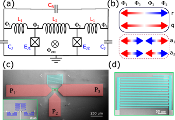
This multi-modal circuit is analyzed at zero flux using four differential modes as shown in Fig.1 (b) where we have assumed the ideal case with i.e. zero asymmetry in the qubit junctions. The modes relevant to us are the mode , where the charge oscillates between the equipotential nodes and , and the ground node, and the mode , where the charge oscillates between nodes and . Here we ignore the high-frequency modes and , which may arise due to the stray capacitance (not shown) from node to and to . The Hamiltonian of the system in the transformed variables and is given by,
| (1) |
where and are the charging energies of the qubit and resonator modes respectively. and are the inductive energies for the qubit and resonator modes respectively, where . The last term is the direct cross-Kerr coupling term between the qubit and resonator mode. The device is operated at integer flux quantum in the quantromon loop to suppress three-wave mixing terms Bergeal et al. (2010); Roy et al. (2017) and dephasing due to flux noise. The Hamiltonian in the second quantised form can now be written as,
| (2) |
where and are the uncoupled frequencies and anharmonicities of the qubit and resonator modes respectively. We analyze this circuit in the limit which implies that the nonlinearity of the resonator mode is extremely weak and can be ignored. The dispersive shift is given by
| (3) |
and weakly depends upon the qubit-resonator detuning via the ratio (see supplementary material). This can enable large dispersive shifts and a wider choice of qubit-resonator detuning without suffering from Purcell decay since the qubit and resonator modes are orthogonal to each other by design (assuming zero or small asymmetry i.e. )
The three samples used in the main results of the paper are fabricated using two different methods and measured using a rectangular waveguide (see supplementary material for details). In Sample A, the individual Josephson junctions in the non-tunable quantromon (Fig. 1(a)) are replaced by SQUIDs so that we can tune . The loop area ratio of the SQUID to the quantromon loop is 6.8%. Since we can only operate at integer flux quanta in the quantromon loop, we can tune the qubit frequency in discrete steps and study the changes in the dispersive shift as a function of qubit-resonator detuning. Note that the readout resonator frequency is very weakly dependent on the value of as and we operate in the regime . We measure the dispersive shift () at different qubit frequencies varying from GHz (0-flux quantum) to GHz (9-flux quantum) and are plotted in Fig. 2(a). The dispersive shift changes from MHz to MHz while the qubit-resonator () detuning changes from GHz to GHz. As the detuning increases linearly with qubit frequency (right to left), the dispersive shift slowly decreases. The asymmetry between the two SQUIDs, can explain the faster changes at smaller detunings as even small asymmetry-induced transverse coupling can produce large dispersive shifts. A theory prediction with junction asymmetry shows good agreement with experiment at smaller detunings. The small deviation at larger detunings is likely due to the asymmetry changing a lot as the two SQUIDs approach half flux quantum in their respective loops due to the finite asymmetry between the junctions of each SQUID. Nevertheless, the data clearly shows that the dispersive shift in the quantromon has a weak dependence on the qubit-resonator detuning.
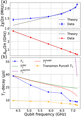
The values at all the operating points are plotted in blue (Fig.2(b)) and shows a steady decrease with increasing qubit frequency. Using asymmetry we compute the (due to the Purcell effect; see supplementary material) and is shown by a solid purple line (visible only on the top right part of the graph). Due to the orthogonality of the qubit and resonator mode and the small asymmetry between the two qubit SQUIDs, the Purcell effect starts to affect the only at small detunings. We then fix the dielectric loss to match the data at the lowest qubit frequency since the Purcell effect can be ignored at this operating point. The Purcell decay along with the dielectric loss () with a quality factor of predicts the trend observed in the data. The prediction is shown by solid red line and follows the trend shown by the experimental data. The disagreement is likely due to enhanced losses at higher qubit frequencies, a trend we typically observe in all our devices. Finally, we also compare the quantromon with that of a transmon coupled to a readout resonator and providing the same dispersive shifts with no Purcell filter. We calculate the coupling required to achieve the measured dispersive shift in the quantromon to estimate the Purcell of the transversely coupled transmon. The transmon Purcell is plotted in yellow and is much lower than the experimentally measured values of the quantromon. This demonstrates the possibility of obtaining strong dispersive shifts at large detunings with protection from Purcell decay.
In Sample A, the Purcell decay due to asymmetry-induced transverse coupling is relevant only for small detunings. To further explore the Purcell effect due to asymmetry in a quantromon, we designed Sample B where only one of the Josephson junctions in Fig. 1(a) is replaced by a SQUID of area . This allows us to tune the asymmetry of the device but the qubit frequency also changes since the effective inductive energy , where , changes as we change the flux quanta . We also increased the coupling of the resonator mode with the environment to enhance the Purcell effect due to asymmetry and to clearly demonstrate the protection at operating points with small asymmetries. As shown in Fig.3(a), a mm long and m wide section is added to the pads P1 and P3 to increase the linewidth of the resonator by times. The of the SQUID was made to be much larger than of the single junction so that we start with a highly asymmetric device at zero flux quantum and slowly decrease the asymmetry as the of the SQUID tunes down with flux.
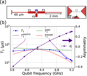
Like the previous experiment, we operated the device at multiple integer flux quanta in the quantromon loop and measured the relaxation times. The device has asymmetry at zero flux ( GHz) as estimated from the room temperature resistance measurements. We then estimate the asymmetry at all other operating points by varying of the SQUID so that the estimated qubit frequency matches with the measured value at that operating point. The extracted asymmetry variation is plotted on the right axis in Fig. 3(b). The correlation between the strength of the asymmetry and experimentally measured (Fig.3(b)) values can be seen. The +5-flux quanta operation point ( GHz)has the minimum asymmetry and the measured is the maximum at this bias point. The behavior can be explained by and shown by the solid purple and green line respectively in Fig.3(b). For this device, is computed using a quality factor and the model used qualitatively captures the trend observed in the data. This demonstrates the in-built Purcell protection of the quantromon along with sufficient tolerance for small asymmetries which are invariably present due to fabrication variabilities. This evades the need for additional circuitry for Purcell filters Walter et al. (2017); Reed et al. (2010); Sunada et al. (2022) that are typically used to engineer the qubit environment in a conventional transmon coupled dispersively to a readout resonator.
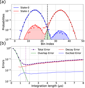
Finally, we discuss experiments on Sample C, a non-tunable quantromon designed to study qubit readout at high photon numbers in the resonator without using a JPA. We extract qubit readout fidelity (also referred to as state assignment fidelity Chen et al. (2023)) by measuring single-shot histograms with the qubit prepared in the ground and excited states as shown in Fig. 4(a). The single-shot histograms are fitted with bimodal Gaussian distributions for state-0 and for state-1 simultaneously to extract , , and Walter et al. (2017). The fitted double Gaussian distributions are plotted in solid colors and the single Gaussians and with dashed black lines. We set the demarcation to be the intersection of the and to calculate the probability for the qubit to be measured in state-A when prepared in state-B. The readout fidelity is then given by
| (4) |
In Fig. 4(a), we show the histograms for the best readout fidelity of we obtained for this sample. The data shown corresponds to a photon number in the readout resonator and an integration time of s. The dispersive shift MHz, and the readout resonator linewidth MHz with MHz and MHz. The readout frequency was chosen to be the mean of the resonator frequencies corresponding to the qubit state-0 and state-1, resulting in a reflected signal phase shift of . The large photon number combined with the large phase shift is clearly reflected in the small error calculated from the overlap of the single Gaussians leading to an ideal readout fidelity Chen et al. (2023) of . This number only accounts for the SNR of the histograms and ignores any state preparation of mixing (excitation and relaxation) errors. We extract the combination of state preparation and mixing errors as , respectively. Since we did not use heralding, we cannot separate state preparation errors from mixing errors which are still quite low for the relatively large photon number used in this experiment.We also plot how these errors change with integration time in Fig. 4(b). We see that overlap error is dominant for small integration lengths as expected while the error at larger times is predominantly due to relaxation with negligible error due to qubit excitation. This suggests that the quantromon is less susceptible to state mixing and ionization Dumas et al. (2024) compared to a standard transmon qubit coupled transversely to readout resonators. A very recent theoretical analysis for similar circuits suggests that the non-perturbative nature of the cross-Kerr term in such circuits may be responsible for suppressing qubit ionization Chapple et al. (2024, 2025). Experiments on several other devices yielded high fidelity numbers (see supplementary material) suggesting that this effect is robust.
In conclusion, we have presented a qubit-resonator system with orthogonal qubit and readout modes and demonstrated three key properties. We show that the device has intrinsic protection from Purcell decay, a weak dependence of dispersive shift on qubit-resonator detuning and demonstrated high readout fidelity () without using a JPA. The quasi-constant dispersive shift can offer more flexibility in choosing the resonator frequency and thus giving larger frequency space for multiplexing qubit readout. The symmetry based intrinsic Purcell protection implies that the dispersive shift can be made larger for faster readout but without requiring Purcell filters, which simplifies the circuitry. The quantromon does need a flux bias to operate at integer flux quantum, but tunable qubits are becoming more common and may provide more options for two-qubit gates. The high readout fidelity without using a JPA suggests the ability to operate at high photon numbers without suffering from qubit ionization. The combination of the three key properties demonstrated in our experiment for the quantromon device may help simplify the architecture of future medium to large-scale processors.
Note.- During the preparation of this manuscript, we learned of an experimental demonstration of a similar device with non-perturbative cross-Kerr term but one which is optimized to implement a non-linear readout resonator and uses two-state readout based on bifurcation physics Wang et al. (2024)
See supplementary material for additional theoretical analysis, experimental data and measurement setup details.
Acknowledgments:- We acknowledge the nanofabrication and central workshop facilities of TIFR. This work is supported by the Department of Atomic Energy of the Government of India under Project No. RTI4003. We also acknowledge support from the Department of Science and Technology, India, via the QuEST program.
Author Declarations
Conflict of Interest
The authors have no conflicts of interest to disclose.
Authors Contribution
Kishor V Salunkhe: Conceptualization (equal); Data curation (lead); Formal analysis (lead); Investigation (equal); Methodology (equal); Software (equal); Writing – original draft (lead); Writing – review and editing (equal). Suman Kundu: Conceptualization (supporting); Data curation (supporting); Methodology (supporting); Writing – review and editing (supporting). Srijita Das: Investigation (supporting); Methodology (supporting); Writing – review and editing (supporting). Jay Deshmukh: Investigation (supporting); Software (equal); Writing – review and editing (supporting). Meghan P Patankar: Methodology (supporting). R Vijay: Conceptualization (equal); Investigation (equal); Supervision (lead); Writing – original draft (supporting); Writing – review and editing (equal).
Data Availability:- The experimental data used in the main paper figures, along with instructions to recreate the plots, are available in Zenodo with the identifier https://doi.org/10.5281/zenodo.14634897. The raw data and the analysis codes related to this study are available from the corresponding authors upon reasonable request.
References
- Preskill (2018) J. Preskill, “Quantum Computing in the NISQ era and beyond,” Quantum 2, 79 (2018).
- Sunada et al. (2022) Y. Sunada, S. Kono, J. Ilves, S. Tamate, T. Sugiyama, Y. Tabuchi, and Y. Nakamura, “Fast Readout and Reset of a Superconducting Qubit Coupled to a Resonator with an Intrinsic Purcell Filter,” Phys. Rev. Applied 17, 044016 (2022).
- Zhou et al. (2021) Y. Zhou, Z. Zhang, Z. Yin, S. Huai, X. Gu, X. Xu, J. Allcock, F. Liu, G. Xi, Q. Yu, H. Zhang, M. Zhang, H. Li, X. Song, Z. Wang, D. Zheng, S. An, Y. Zheng, and S. Zhang, “Rapid and unconditional parametric reset protocol for tunable superconducting qubits,” Nat Commun 12, 5924 (2021), publisher: Nature Publishing Group.
- Li and Benjamin (2017) Y. Li and S. C. Benjamin, “Efficient Variational Quantum Simulator Incorporating Active Error Minimization,” Phys. Rev. X 7, 021050 (2017).
- Blais et al. (2004) A. Blais, R.-S. Huang, A. Wallraff, S. M. Girvin, and R. J. Schoelkopf, “Cavity quantum electrodynamics for superconducting electrical circuits: An architecture for quantum computation,” Phys. Rev. A 69, 062320 (2004).
- Wallraff et al. (2005) A. Wallraff, D. I. Schuster, A. Blais, L. Frunzio, J. Majer, M. H. Devoret, S. M. Girvin, and R. J. Schoelkopf, “Approaching Unit Visibility for Control of a Superconducting Qubit with Dispersive Readout,” Phys. Rev. Lett. 95, 060501 (2005).
- Boissonneault, Gambetta, and Blais (2009) M. Boissonneault, J. M. Gambetta, and A. Blais, “Dispersive regime of circuit QED: Photon-dependent qubit dephasing and relaxation rates,” Phys. Rev. A 79, 013819 (2009).
- Zueco et al. (2009) D. Zueco, G. M. Reuther, S. Kohler, and P. Hänggi, “Qubit-oscillator dynamics in the dispersive regime: Analytical theory beyond the rotating-wave approximation,” Phys. Rev. A 80, 033846 (2009).
- Jeffrey et al. (2014) E. Jeffrey, D. Sank, J. Y. Mutus, T. C. White, J. Kelly, R. Barends, Y. Chen, Z. Chen, B. Chiaro, A. Dunsworth, A. Megrant, P. J. J. O’Malley, C. Neill, P. Roushan, A. Vainsencher, J. Wenner, A. N. Cleland, and J. M. Martinis, “Fast Accurate State Measurement with Superconducting Qubits,” Phys. Rev. Lett. 112, 190504 (2014).
- Walter et al. (2017) T. Walter, P. Kurpiers, S. Gasparinetti, P. Magnard, A. Potočnik, Y. Salathé, M. Pechal, M. Mondal, M. Oppliger, C. Eichler, and A. Wallraff, “Rapid High-Fidelity Single-Shot Dispersive Readout of Superconducting Qubits,” Phys. Rev. Applied 7, 054020 (2017).
- Koch et al. (2007) J. Koch, T. M. Yu, J. Gambetta, A. A. Houck, D. I. Schuster, J. Majer, A. Blais, M. H. Devoret, S. M. Girvin, and R. J. Schoelkopf, “Charge-insensitive qubit design derived from the Cooper pair box,” Phys. Rev. A 76, 042319 (2007).
- Gambetta et al. (2008) J. Gambetta, A. Blais, M. Boissonneault, A. A. Houck, D. I. Schuster, and S. M. Girvin, “Quantum trajectory approach to circuit QED: Quantum jumps and the Zeno effect,” Phys. Rev. A 77, 012112 (2008).
- E. M. Purcell (1946) E. M. Purcell, “Spontaneous Emission Probabilities at Radio Frequencies,,” Phys. Rev. 69, 674–674 (1946).
- Reed et al. (2010) M. D. Reed, B. R. Johnson, A. A. Houck, L. DiCarlo, J. M. Chow, D. I. Schuster, L. Frunzio, and R. J. Schoelkopf, “Fast reset and suppressing spontaneous emission of a superconducting qubit,” Applied Physics Letters 96, 203110 (2010).
- Gard et al. (2019) B. T. Gard, K. Jacobs, J. Aumentado, and R. W. Simmonds, “Fast, High-Fidelity, Quantum Non-demolition Readout of a Superconducting Qubit Using a Transverse Coupling,” (2019).
- Didier, Bourassa, and Blais (2015) N. Didier, J. Bourassa, and A. Blais, “Fast Quantum Nondemolition Readout by Parametric Modulation of Longitudinal Qubit-Oscillator Interaction,” Phys. Rev. Lett. 115, 203601 (2015).
- Touzard et al. (2019) S. Touzard, A. Kou, N. E. Frattini, V. V. Sivak, S. Puri, A. Grimm, L. Frunzio, S. Shankar, and M. H. Devoret, “Gated Conditional Displacement Readout of Superconducting Qubits,” Phys. Rev. Lett. 122, 080502 (2019).
- Bergeal et al. (2010) N. Bergeal, R. Vijay, V. E. Manucharyan, I. Siddiqi, R. J. Schoelkopf, S. M. Girvin, and M. H. Devoret, “Analog information processing at the quantum limit with a Josephson ring modulator,” Nature Phys 6, 296–302 (2010).
- Roy et al. (2017) T. Roy, S. Kundu, M. Chand, S. Hazra, N. Nehra, R. Cosmic, A. Ranadive, M. P. Patankar, K. Damle, and R. Vijay, “Implementation of Pairwise Longitudinal Coupling in a Three-Qubit Superconducting Circuit,” Phys. Rev. Applied 7, 054025 (2017).
- Pfeiffer et al. (2024) F. Pfeiffer, M. Werninghaus, C. Schweizer, N. Bruckmoser, L. Koch, N. Glaser, G. Huber, D. Bunch, F. Haslbeck, M. Knudsen, G. Krylov, K. Liegener, A. Marx, L. Richard, J. Romeiro, F. Roy, J. Schirk, C. Schneider, M. Singh, L. Södergren, I. Tsitsilin, F. Wallner, C. Riofrío, and S. Filipp, “Efficient Decoupling of a Nonlinear Qubit Mode from Its Environment,” Phys. Rev. X 14, 041007 (2024).
- Vijay, Devoret, and Siddiqi (2009) R. Vijay, M. H. Devoret, and I. Siddiqi, “Invited Review Article: The Josephson bifurcation amplifier,” Review of Scientific Instruments 80, 111101 (2009).
- Dassonneville et al. (2020) R. Dassonneville, T. Ramos, V. Milchakov, L. Planat, E. Dumur, F. Foroughi, J. Puertas, S. Leger, K. Bharadwaj, J. Delaforce, C. Naud, W. Hasch-Guichard, J. J. Garcia-Ripoll, N. Roch, and O. Buisson, “Fast High-Fidelity Quantum Nondemolition Qubit Readout via a Nonperturbative Cross-Kerr Coupling,” Phys. Rev. X 10, 011045 (2020).
- Kundu et al. (2019) S. Kundu, N. Gheeraert, S. Hazra, T. Roy, K. V. Salunkhe, M. P. Patankar, and R. Vijay, “Multiplexed readout of four qubits in 3D circuit QED architecture using a broadband Josephson parametric amplifier,” Applied Physics Letters 114, 172601 (2019).
- Chen et al. (2023) L. Chen, H.-X. Li, Y. Lu, C. W. Warren, C. J. Križan, S. Kosen, M. Rommel, S. Ahmed, A. Osman, J. Biznárová, A. Fadavi Roudsari, B. Lienhard, M. Caputo, K. Grigoras, L. Grönberg, J. Govenius, A. F. Kockum, P. Delsing, J. Bylander, and G. Tancredi, “Transmon qubit readout fidelity at the threshold for quantum error correction without a quantum-limited amplifier,” npj Quantum Inf 9, 1–7 (2023), publisher: Nature Publishing Group.
- Dumas et al. (2024) M. F. Dumas, B. Groleau-Paré, A. McDonald, M. H. Muñoz-Arias, C. Lledó, B. D’Anjou, and A. Blais, “Measurement-Induced Transmon Ionization,” Phys. Rev. X 14, 041023 (2024), publisher: American Physical Society.
- Chapple et al. (2024) A. A. Chapple, A. McDonald, M. H. Muñoz-Arias, and A. Blais, “Robustness of longitudinal transmon readout to ionization,” (2024), arXiv:2412.07734 [quant-ph].
- Chapple et al. (2025) A. A. Chapple, O. Benhayoune-Khadraoui, S. Richer, and A. Blais, “Balanced cross-Kerr coupling for superconducting qubit readout,” (2025), arXiv:2501.09010 [quant-ph].
- Wang et al. (2024) C. Wang, F.-M. Liu, H. Chen, Y.-F. Du, C. Ying, J.-W. Wang, Y.-H. Huo, C.-Z. Peng, X. Zhu, M.-C. Chen, C.-Y. Lu, and J.-W. Pan, “99.9%-fidelity in measuring a superconducting qubit,” (2024), arXiv:2412.13849 [quant-ph].