This paper was converted on www.awesomepapers.org from LaTeX by an anonymous user.
Want to know more? Visit the Converter page.

Uplink Performance of RIS-aided Cell-Free Massive MIMO System Over Spatially Correlated Channels

Enyu Shi, Jiayi Zhang, Zhe Wang, Derrick Wing Kwan Ng, , and Bo Ai E. Shi, J. Zhang, and Z. Wang are with the School of Electronics and Information Engineering, Beijing Jiaotong University, Beijing 100044, P. R. China. (e-mail: jiayizhang@bjtu.edu.cn).D. W. K. Ng is with the School of Electrical Engineering and Telecommunications, University of New South Wales, NSW 2052, Australia. (e-mail: w.k.ng@unsw.edu.au).B. Ai is with the State Key Laboratory of Rail Traffic Control and Safety, Beijing Jiaotong University, Beijing 100044, China.
Abstract

We consider a practical spatially correlated reconfigurable intelligent surface (RIS)-aided cell-free (CF) massive multiple-input-multiple-output (mMIMO) system with multi-antenna access points (APs) over spatially correlated Rician fading channels. The minimum mean square error (MMSE) channel estimator is adopted to estimate the aggregated RIS channels. Then, we investigate the uplink spectral efficiency (SE) with the maximum ratio (MR) and the local minimum mean squared error (L-MMSE) combining at the APs and obtain the closed-form expression for characterizing the performance of the former. The accuracy of our derived analytical results has been verified by extensive Monte-Carlo simulations. Our results show that increasing the number of RIS elements is always beneficial, but with diminishing returns when the number of RIS elements is sufficiently large. Furthermore, the effect of the number of AP antennas on system performance is more pronounced under a small number of RIS elements, while the spatial correlation of RIS elements imposes a more severe negative impact on the system performance than that of the AP antennas.

I Introduction

Cell-free (CF) massive multiple-input-multiple-output (mMIMO) has recently been introduced as one of the most promising technologies for enabling beyond-fifth-generation (B5G) wireless communication systems [1]. In practice, cell-free systems are capable of serving a large number of user equipments (UEs) and improving the associated communication quality by shortening the distances between the UEs and the APs [2, 3]. Meanwhile, reconfigurable intelligent surface (RIS) has recently been introduced as a new paradigm which can establish reconfigurable wireless channels/radio propagation environment [4]. In particular, the RIS can be deployed in scenarios with harsh communication environments, such as channels with large obstructions or interference to significantly improve communication quality [4, 5, 6].

Recently, a number of studies have focused on how to jointly exploit the advantages of RIS and CF mMIMO to enhance the network performance. For instance, in [5], the authors introduced an RIS-aided CF wireless energy transfer framework to improve the energy efficiency and the communication system quality. Also, in [7], the authors deployed multiple RISs to assist CF massive MIMO and proposed an iterative resource allocation algorithm to address the system sum-rate optimization problem. Besides, in [8], the authors proposed a new channel estimation method for RIS-aided CF communications, which can estimate the involved end-to-end channels by switching each element in turn. However, none of the aforementioned studies considered the effect of spatial correlation of RIS on system performance. Indeed, spatial correlations among RIS elements naturally exist in practice due to their sub-wavelength structure. As such, in [9], a sinc function-based model was proposed to capture the spatial correlations that are determined by the spacing among RIS elements. Based on this, in [10], the authors proposed an aggregated channel estimation method and considered the performance of a CF system assisted by a single RIS with spatially correlated elements. However, only Rayleigh fading channels with single-antenna APs were considered and their results are not applicable to the practical RIS-aided CF mMIMO systems. Therefore, there is an emerging need to consider the impact of the correlations of the RIS elements and AP antennas to study the system performance limit.

To address the above limitations, we consider an RIS-aided CF mMIMO system with multi-antenna APs over spatially correlated Rician fading channels. More specifically, we propose the minimum mean square error (MMSE)-based channel estimation to estimate the aggregated channels between the APs and the UEs. Then, we utilize the maximum ratio (MR) and the local minimum mean squared error (L-MMSE) combining at the APs to obtain the uplink spectral efficiency (SE) and obtain the closed-form expressions for that adopting MR combining. The results show that increasing the number of RIS elements or AP antennas can always improve the system performance. Moreover, the spatial correlation among RIS elements dominates the system performance more than that of AP antennas. Finally, compared with MR combining, L-MMSE combining enjoys a better performance with a large number of RIS elements at the cost of higher computational complexity.

Notation: The superscripts 𝐱H\mathbf{x}^{H} and xx^{\mathrm{*}} are used to represent conjugate transpose and conjugate, respectively. The matrices and column vectors are denoted by boldface uppercase letters 𝐗\mathbf{X} and boldface lowercase letters 𝐱\mathbf{x}, respectively. The mod(,){\rm{mod}}\left({\cdot,\cdot}\right), \left\|\cdot\right\|, and \left\lfloor\cdot\right\rfloor denote the modulus operation, the Euclidean norm and the truncated argument, respectively. tr(){\rm{tr}}\left(\cdot\right), 𝔼{}\mathbb{E}\left\{\cdot\right\}, and Cov{}{\rm{Cov}}\left\{\cdot\right\} are the trace, expectation and covariance operators. \otimes denotes the Kronecker products. Finally, the circularly symmetric complex Gaussian random variable xx with variance σ2\sigma^{2} is denoted by x𝒞𝒩(0,σ2)x\sim\mathcal{C}\mathcal{N}\left({0,{\sigma^{2}}}\right).

II System Model

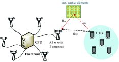
As shown in Figure 1, we consider an RIS-aided CF mMIMO system consisting of MM APs, one RIS, and KK UEs. The RIS has NN reflective elements that can introduce some phase shifts to the incident signals. We consider that each AP is equipped with LL antennas and each UE is equipped with a single antenna. The central processing unit (CPU) connect to all APs via fronthaul links. The standard time division duplex (TDD) protocol is adopted, where τc\tau_{c} is the length of each coherence block. We assume that τp\tau_{p} symbols are exploited for the channel estimation phase in the uplink (UL) and τu=τcτp\tau_{u}=\tau_{c}-\tau_{p} symbols are utilized for data transmission.

Let 𝐠mkL{{\bf{g}}_{mk}}\in{\mathbb{C}}{{}^{L}} denote the direct link channel between UE kk and AP mm. 𝐇mN×L{{\bf{H}}_{m}}\in{\mathbb{C}}{{}^{N\times L}} denote the channel matrix from AP mm to the RIS and 𝐳kN{{\bf{z}}_{k}}\in{\mathbb{C}}{{}^{N}} denote the channel from UE kk to the RIS, respectively. We consider a realistic model to capture the spatial correlation among the RIS elements [9]. Meanwhile, the spatial correlation due to the AP multiple antennas is also considered in this paper. We assume that AP-UE channels are Rayleigh fading whereas RIS-UE and AP-RIS channels are Rician fading. Then, the channels 𝐠mk{{\bf{g}}_{mk}}, 𝐳k{{\bf{z}}_{k}}, and 𝐇m{{\bf{H}}_{m}} can be modeled as

𝐠mk\displaystyle{{\bf{g}}_{mk}} 𝒞𝒩(0,𝐑mk),\displaystyle\sim{\cal C}{\cal N}\left({0,{{\mathbf{R}}_{mk}}}\right), (1)
𝐇m\displaystyle{{\bf{H}}_{m}} =𝐇¯m+𝐇~m,𝐳k=𝚯k𝐳¯k+𝐳~k,\displaystyle={{{\bf{\bar{H}}}}_{m}}+{{{\bf{\tilde{H}}}}_{m}},\;{{\bf{z}}_{k}}={{\bf{\Theta}}_{k}}{{{\bf{\bar{z}}}}_{k}}+{{{\bf{\tilde{z}}}}_{k}}, (2)

where 𝐑mkL×L{\mathbf{R}}_{mk}\in{\mathbb{C}}{{}^{L\times L}} is the spatial correlation matrix of AP antennas and βmk=tr(𝐑mk)/L{\beta_{mk}}={{{\rm{tr}}\left({{{\bf{R}}_{mk}}}\right)}\mathord{\left/{\vphantom{{{\rm{tr}}\left({{{\bf{R}}_{mk}}}\right)}L}}\right.\kern-1.2pt}L} is the large-scale fading coefficient between AP mm and UE kk. 𝐇¯mN×L{{{\bf{\bar{H}}}}_{m}}\in{{\mathbb{C}}^{N\times L}} and 𝐳¯kN{{{\bf{\bar{z}}}}_{k}}\in{{\mathbb{C}}^{N}} represent the deterministic LoS component of AP-RIS and RIS-UE channels, respectively. 𝐇~m𝒞𝒩(𝟎,𝐑~m){{{\bf{\tilde{H}}}}_{m}}\sim{\cal C}{\cal N}\left({{\bf{0}},{{{\bf{\tilde{R}}}}_{m}}}\right) and 𝐳~k𝒞𝒩(𝟎,𝐑~k){{{\bf{\tilde{z}}}}_{k}}\sim{\cal C}{\cal N}\left({{\bf{0}},{{{\bf{\tilde{R}}}}_{k}}}\right) are the NLoS components, where 𝐑~m=1LNβm(𝐑mT𝐑r)NL×NL{{{\bf{\tilde{R}}}}_{m}}=\frac{1}{{LN{\beta_{m}}}}\left({{\bf{R}}_{m}^{T}\otimes{{\bf{R}}_{r}}}\right)\in{{\mathbb{C}}^{NL\times NL}} and 𝐑~k=βk𝐑N×N{{{\bf{\tilde{R}}}}_{k}}={\beta_{k}}{\bf{R}}\in{{\mathbb{C}}^{N\times N}} [11, 12]. βm{{\beta_{m}}} and βk{{\beta_{k}}} denote the large-scale fading coefficients from AP mm and UE kk to RIS, respectively. Note that 𝐑m{{\bf{R}}_{m}} and 𝐑r=βm𝐑{{{\bf{R}}_{r}}={\beta_{m}}\bf{R}} denote the correlation matrices of the AP side and RIS side, respectively. 𝐑N×N{\mathbf{R}}\in{{\mathbb{C}}^{N\times N}} characterizes the spatial correlation of the RIS which has the (m,n)\left({m^{\prime},n^{\prime}}\right)-th element as [𝐑]mn=sinc(2𝐮m𝐮n/λ){{\left[\mathbf{R}\right]_{m^{\prime}n^{\prime}}}={\rm{sinc}}\left({{{2\left\|{{{\mathbf{u}}_{m^{\prime}}}-{{\mathbf{u}}_{n^{\prime}}}}\right\|}\mathord{\left/{\vphantom{{2\left\|{{{\mathbf{u}}_{m^{\prime}}}-{{\mathbf{u}}_{n^{\prime}}}}\right\|}\lambda}}\right.\kern-1.2pt}\lambda}}\right)}, where sinc(x)=sin(πx)/(πx){{\rm{sinc}}\left(x\right)={{\sin\left({\pi x}\right)}\mathord{\left/{\vphantom{{\sin\left({\pi x}\right)}{\left({\pi x}\right)}}}\right.\kern-1.2pt}{\left({\pi x}\right)}}} denotes the sinc function and λ{\lambda} denotes the carrier wavelength [9]. Besides, 𝐮x=[0,mod(x1,NH)dH,(x1)/NHdV]T{{\mathbf{u}_{x}}\!=\!{\left[{0,\bmod\left({x-1,{N_{H}}}\right){d_{H}},\left\lfloor{{{\left({x-1}\right)}\mathord{\left/{\vphantom{{\left({x-1}\right)}{{N_{H}}}}}\right.\kern-1.2pt}{{N_{H}}}}}\right\rfloor{d_{V}}}\right]^{T}}}, x{m,n}x\!\in\!\left\{{m^{\prime},n^{\prime}}\right\} is the position vector, where NV{N_{V}} and NH{N_{H}} are the number of elements at RIS in each column and row, respectively, such that N=NH×NV{N={N_{H}}\times{N_{V}}}. Moreover, 𝚯k=diag(ejθ1k,,ejθNk)N×N{{\bf{\Theta}}_{k}}={\rm{diag}}\left({{e^{j{\theta_{1k}}}},\cdots,{e^{j{\theta_{Nk}}}}}\right)\in{{\mathbb{C}}^{N\times N}}, where θnk[π,π]{\theta_{nk}}\in\left[{-\pi,\pi}\right] is the phase-shift of the LoS component between UE kk and the nn-th element of RIS caused by the small change in the UE location [13]. We assume that all elements of 𝚯k{{\bf{\Theta}}_{k}} are idential [13] such that the LoS component can be written as 𝐳¯kejθk{{{\bf{\bar{z}}}}_{k}}{e^{j{\theta_{k}}}}.

Let 𝚽=diag(ejφ1,ejφ2,,ejφN){\mathbf{\Phi}={\rm{diag}}\left({{e^{j{\varphi_{1}}}},{e^{j{\varphi_{2}}}},\cdots,{e^{j{\varphi_{N}}}}}\right)} denote the phase shift matrix of RIS, where φn[π,π],n{1,,N}{\varphi_{n}}\in\left[{-\pi,\pi}\right],\forall n\in\left\{{1,\ldots,N}\right\}, denotes the phase shift introduced by the nn-th RIS element. Thus, the total uplink aggregated channel between UE kk and AP mm can be formulated as

𝐨mk=𝐠mk+𝐇mH𝚽𝐳k,m,k,\displaystyle{{\bf{o}}_{mk}}={{\bf{g}}_{mk}}+{\bf{H}}_{m}^{H}{\bf{\Phi}}{{\bf{z}}_{k}},\forall m,k, (3)

which consists of a direct link between AP mm and UE kk and a cascaded link reflected by the RIS. By mathematical derivation, the end-to-end channel is obtained as

𝐨mk=𝐠mk+𝐇mH𝚽𝐳k\displaystyle{{\bf{o}}_{mk}}={{\bf{g}}_{mk}}+{\bf{H}}_{m}^{H}{\bf{\Phi}}{{\bf{z}}_{k}}
=𝐠mk+(𝐇¯m+𝐇~m)H𝚽(𝐳¯kejθk+𝐳~k)\displaystyle={{\bf{g}}_{mk}}+{\left({{{{\bf{\bar{H}}}}_{m}}+{{{\bf{\tilde{H}}}}_{m}}}\right)^{H}}{\bf{\Phi}}\left({{{{\bf{\bar{z}}}}_{k}}{{e^{j{\theta_{k}}}}}+{{{\bf{\tilde{z}}}}_{k}}}\right)
=𝐇¯mH𝚽𝐳¯k𝐨¯mkejθk+𝐠mk+𝐇¯mH𝚽𝐳~k+𝐇~mH𝚽𝐳¯kejθk+𝐇~mH𝚽𝐳~k𝐨~mk.\displaystyle=\!\underbrace{{\bf{\bar{H}}}_{m}^{H}{\bf{\Phi}}{{{\bf{\bar{z}}}}_{k}}}_{{{{\bf{\bar{o}}}}_{mk}}}{e^{j{\theta_{k}}}}\!+\!\underbrace{{{\bf{g}}_{mk}}\!+\!{\bf{\bar{H}}}_{m}^{H}{\bf{\Phi}}{{{\bf{\tilde{z}}}}_{k}}\!+\!{\bf{\tilde{H}}}_{m}^{H}{\bf{\Phi}}{{{\bf{\bar{z}}}}_{k}}{e^{j{\theta_{k}}}}\!\!+\!{\bf{\tilde{H}}}_{m}^{H}{\bf{\Phi}}{{{\bf{\tilde{z}}}}_{k}}}_{{{{\bf{\tilde{o}}}}_{mk}}}. (4)

We consider that UEs move slowly, so the LoS component 𝐨¯mk{{{{\bf{\bar{o}}}}_{mk}}} is slow time-varying and is known at the APs [13, 14]. In the following, we first analyze the second-order statistic of unknown 𝐨~mk{{\bf{\tilde{o}}}_{mk}} that will be handy for the analysis in the sequel.

Theorem 1.

The covariance matrix of the second term 𝐨~mk{{{{\bf{\tilde{o}}}}_{mk}}} in (4) can be obtained as

𝔼{𝐨~mk𝐨~mkH}=𝐑mk+𝐇¯mH𝚽𝐑~k𝚽H𝐇¯m+𝐐mk1+𝐐mk2𝐑mko.\displaystyle\mathbb{E}\left\{{{{{{\bf{\tilde{o}}}}_{mk}}{{{\bf{\tilde{o}}}}^{H}_{mk}}}}\right\}\!=\!\underbrace{{{\bf{R}}_{mk}}\!+\!{\bf{\bar{H}}}_{m}^{H}\mathbf{\Phi}{{{\bf{\tilde{R}}}}_{k}}{\mathbf{\Phi}^{H}}{{{\bf{\bar{H}}}}_{m}}\!+\!{\bf{Q}}_{mk}^{1}\!+\!{\bf{Q}}_{mk}^{2}}_{{\bf{R}}_{mk}^{o}}. (5)
Proof:

The proof is given in Appendix A. ∎

Remark 1.

Note that the mean and covariance matrix of the aggregated channel 𝐨mk{{{{\bf{o}}}_{mk}}} can be obtained at AP in each coherence block, so we can utilize them to estimate the end-to-end aggregated channel in the next subsection.

Refer to caption
Figure 1: RIS-aided CF mMIMO system with multi-antenna APs.

II-A Uplink Channel Estimation

We adopt τp\tau_{p} pilot sequences which are mutually orthogonal for channel estimation in each coherence block. All the UEs share the same τp\tau_{p} orthogonal pilot sequences. In particular, the pilot sequence of UE kk is denoted by ϕkτp{\bm{\phi}_{k}}\in{{\mathbb{C}}^{{\tau_{p}}}} and satisfies ϕk2=τp{{\left\|{{\bm{\phi}_{k}}}\right\|^{2}}={\tau_{p}}}. Let 𝒫k{{\cal P}_{k}} denotes the index subset of UEs which adopts the same pilot sequence as UE kk including itself because of K>τpK>{\tau_{p}}. The received pilot signals 𝐘mpL×τp{\bf{Y}}_{m}^{p}\in{\mathbb{C}^{L\times{\tau_{p}}}} from all the UEs at AP mm as

𝐘mp=k=1Kp^k𝐨mkϕkT+𝐍mp,\displaystyle{\bf{Y}}_{m}^{p}=\sum\limits_{k=1}^{K}{\sqrt{{{\hat{p}}_{k}}}{{\bf{o}}_{mk}}}{\bm{\phi}}_{k}^{T}+{\bf{N}}_{m}^{p}, (6)

where p^k{{{\hat{p}}_{k}}} is the pilot transmit power of UE kk, 𝐍mpL×τp{\bf{N}}_{m}^{p}\in{\mathbb{C}^{L\times{\tau_{p}}}} is the additive noise with independent 𝒞𝒩(0,σ2){\cal C}{\cal N}\left({0,{\sigma^{2}}}\right) entries, and σ2{\sigma^{2}} is the noise power. We multiply the received signal by ϕk{{\bm{\phi}}_{k}^{*}} at AP mm to estimate 𝐨mk{{{\bf{o}}_{mk}}} and the results can be obtained as

𝐲mp=𝐘mpϕk=p^kτp𝐨mk+i𝒫k\{k}p^iτp𝐨mi+𝐧mp,\displaystyle{\bf{y}}_{m}^{p}\!=\!{\bf{Y}}_{m}^{p}{\bm{\phi}}_{k}^{*}\!=\!\sqrt{{{\hat{p}}_{k}}}{\tau_{p}}{{\bf{o}}_{mk}}\!+\!\!\sum\limits_{i\in{{\cal P}_{k}}\backslash\left\{k\right\}}\!\!{\sqrt{{{\hat{p}}_{i}}}{\tau_{p}}{{\bf{o}}_{mi}}}\!+\!{\bf{n}}_{m}^{p}, (7)

where 𝐧mp=𝐍mpϕk𝒞𝒩(0,σ2𝐈L){\bf{n}}_{m}^{p}={\bf{N}}_{m}^{p}{\bm{\phi}}_{k}^{*}\sim{\cal C}{\cal N}\left({0,{\sigma^{2}}{{\bf{I}}_{L}}}\right). Based on (7), if 𝐨¯mk{{{{\bf{\bar{o}}}}_{mk}}}, 𝐑mko{\bf{R}}_{mk}^{o}, and φk{{\varphi_{k}}} are available at AP mm, we utilize the phase-aware MMSE channel estimator to estimate the effective channel 𝐨mk{{\bf{o}}_{mk}} as

𝐨^mk=𝐨¯mkejφk+p^k𝐑mko𝚿mk1(𝐲mkp𝐲¯mkp),\displaystyle{{{\bf{\hat{o}}}}_{mk}}={{{\bf{\bar{o}}}}_{mk}}{e^{j{\varphi_{k}}}}+\sqrt{{\hat{p}_{k}}}{\bf{R}}_{mk}^{o}{\bf{\Psi}}_{mk}^{-1}\left({{\bf{y}}_{mk}^{p}-{\bf{\bar{y}}}_{mk}^{p}}\right), (8)

where 𝐲¯mkp=i𝒫kp^iτp𝐨¯miejφi{\bf{\bar{y}}}_{mk}^{p}=\sum\nolimits_{i\in{{\cal P}_{k}}}{\sqrt{{{\hat{p}}_{i}}}}{\tau_{p}}{{{\bf{\bar{o}}}}_{mi}}{e^{j{\varphi_{i}}}} and 𝚿mk=i𝒫kp^iτp𝐑mio+σ2𝐈L{{\bf{\Psi}}_{mk}}=\sum\nolimits_{i\in{{\cal P}_{k}}}{{{\hat{p}}_{i}}{\tau_{p}}{\bf{R}}_{mi}^{o}}+{\sigma^{2}}{{\bf{I}}_{L}}. The estimated channel 𝐨^mk{{{\bf{\hat{o}}}}_{mk}} and the estimation error 𝐨~mk=𝐨mk𝐨^mk{{{\bf{\tilde{o}}}}_{mk}}={{\bf{o}}_{mk}}-{{{\bf{\hat{o}}}}_{mk}} are independent random variable with

𝔼{𝐨^mk|φk}=𝐨¯mkejφk,Cov{𝐨^mk|φk}=p^kτp𝛀mk,\displaystyle\mathbb{E}\left\{{{{{\bf{\hat{o}}}}_{mk}}\left|{{\varphi_{k}}}\right.}\right\}={{{\bf{\bar{o}}}}_{mk}}{e^{j{\varphi_{k}}}},{\rm{Cov}}\left\{{{{{\bf{\hat{o}}}}_{mk}}\left|{{\varphi_{k}}}\right.}\right\}={{\hat{p}}_{k}}{\tau_{p}}{{\bf{\Omega}}_{mk}},
𝔼{𝐨~mk}=𝟎,Cov{𝐨~mk}=𝐂mk,\displaystyle\mathbb{E}\left\{{{{{\bf{\tilde{o}}}}_{mk}}}\right\}={\bf{0}},\quad\quad\quad\quad\;\;\;{\rm{Cov}}\left\{{{{{\bf{\tilde{o}}}}_{mk}}}\right\}={{\bf{C}}_{mk}},

where 𝛀mk=𝐑mko𝚿mk1𝐑mko{{\bf{\Omega}}_{mk}}={\bf{R}}_{mk}^{o}{\bf{\Psi}}_{mk}^{-1}{\bf{R}}_{mk}^{o} and 𝐂mk=𝐑mkop^kτp𝐑mko𝚿mk1𝐑mko{{\bf{C}}_{mk}}={\bf{R}}_{mk}^{o}-{{\hat{p}}_{k}}{\tau_{p}}{\bf{R}}_{mk}^{o}{\bf{\Psi}}_{mk}^{-1}{\bf{R}}_{mk}^{o}.

II-B Uplink Data Transmission

In the uplink, we consider that the UEs transmit the uplink data to all the APs simultaneously. Then, the received signal at AP mm is obtained as

𝐲m=k=1K𝐨mksk+𝐧m,\displaystyle{{\bf{y}}_{m}}=\sum\limits_{k=1}^{K}{{{\bf{o}}_{mk}}}{s_{k}}+{{\bf{n}}_{m}}, (9)

where sk𝒞𝒩(0,pk){s_{k}}\sim{\cal C}{\cal N}\left({0,{p_{k}}}\right) denotes the uplink signal transmitted by UE kk with power pk=𝔼{|sk|2}{p_{k}}=\mathbb{E}\left\{{{{\left|{{s_{k}}}\right|}^{2}}}\right\}. 𝐧m𝒞𝒩(𝟎,σ2𝐈L){{\bf{n}}_{m}}\sim{\cal C}{\cal N}\left({{\bf{0}},{\sigma^{2}}{{\bf{I}}_{L}}}\right) denotes the additive noise. We consider that each AP can process the uplink data locally and intermediately with a combining vector. We adopt 𝐯mkL{{\bf{v}}_{mk}}\in{\mathbb{C}^{L}} denoting the combining vector which is designed by AP mm for UE kk and then AP mm can obtain the local estimate of sk{s_{k}} as

s~mk=𝐯mkH𝐲m=k=1K𝐯mkH𝐨mksk+𝐯mkH𝐧m.\displaystyle{{\tilde{s}}_{mk}}={\bf{v}}_{mk}^{H}{{\bf{y}}_{m}}=\sum\limits_{k=1}^{K}{{\bf{v}}_{mk}^{H}{{\bf{o}}_{mk}}}{s_{k}}+{\bf{v}}_{mk}^{H}{{\bf{n}}_{m}}. (10)

Any combining vector is available for (10) and the local channel state information (CSI) in AP mm can be used to design 𝐯mk{{\bf{v}}_{mk}}. Here, we consider the MR combining with 𝐯mk=𝐨^mk{{\bf{v}}_{mk}}={\bf{\hat{o}}}_{mk} and the L-MMSE combining introduced in [15] as

𝐯mk=pk(i=1Kpi(𝐨^mi(𝐨^mi)H+𝐂mi)+σ2𝐈L)1𝐨^mk.\displaystyle{{\bf{v}}_{mk}}\!=\!{p_{k}}{\left({\sum\limits_{i=1}^{K}{{p_{i}}\!\left({{{{\bf{\hat{o}}}}_{mi}}{{\left({{{{\bf{\hat{o}}}}_{mi}}}\right)}^{H}}\!\!+\!{{\bf{C}}_{mi}}}\right)}\!+\!{\sigma^{2}}{{\bf{I}}_{L}}}\right)^{-1}}\!\!{{{\bf{\hat{o}}}}_{mk}}. (11)

Note that (11) can minimize MSEmk=𝔼{|sk𝐯mkH𝐲m|2|{𝐨^mk}}{\rm{MS}}{{\rm{E}}_{mk}}=\mathbb{E}\left\{{\left.{{{\left|{{s_{k}}-{\bf{v}}_{mk}^{H}{{\bf{y}}_{m}}}\right|}^{2}}}\right|\left\{{{{{\bf{\hat{o}}}}_{mk}}}\right\}}\right\} and is optimal for the MMSE estimation.

After the MR/L-MMSE combining, all APs convey the local estimates s~mk{{\tilde{s}}_{mk}} in (10) to the CPU. To further mitigate the inter-user interference [3], s~mk{{\tilde{s}}_{mk}} are linearly weighted with the large-scale fading decoding (LSFD) coefficients amk{a_{mk}^{*}}\in\mathbb{C} as

s^k=m=1Mamks~mk=𝐚kH𝐮kksk+ikK𝐚kH𝐮kisi+𝐧k,\displaystyle{{\hat{s}}_{k}}=\sum\limits_{m=1}^{M}{a_{mk}^{*}}{{\tilde{s}}_{mk}}={\bf{a}}_{k}^{H}{{\bf{u}}_{kk}}{s_{k}}+\sum\limits_{i\neq k}^{K}{{\bf{a}}_{k}^{H}{{\bf{u}}_{ki}}{s_{i}}}+{{\bf{n}}_{k}}, (12)

where 𝐮ki=[𝐯1kH𝐨1i,,𝐯MkH𝐨Mi]TM{{\bf{u}}_{ki}}={\left[{{\bf{v}}_{1k}^{H}{{\bf{o}}_{1i}},\cdots,{\bf{v}}_{Mk}^{H}{{\bf{o}}_{Mi}}}\right]^{T}}\in\mathbb{C}{{}^{M}}, 𝐧k=m=1Mamk𝐯mkH𝐧m{{\bf{n}}_{k}}=\sum\nolimits_{m=1}^{M}{a_{mk}^{*}{\bf{v}}_{mk}^{H}{{\bf{n}}_{m}}}, and 𝐚k=[a1k,,aMk]TM{{\bf{a}}_{k}}={\left[{{a_{1k}},\cdots,{a_{Mk}}}\right]^{T}}\in\mathbb{C}{{}^{M}} denotes the LSFD coefficient vector, respectively.

III Performance Analysis

In this section, we analyze the uplink performance of the RIS-aided CF mMIMO system with the MR combining scheme and investigate the impact of spatial correlation. Based on (12), the uplink achievable SE lower bound of UE kk can be obtained by utilizing the use-and-then-forget (UatF) bound [3, 16] as follows

SEk=τuτclog2(1+γk),\displaystyle{\rm{S}}{{\rm{E}}_{k}}=\frac{{{\tau_{u}}}}{{{\tau_{c}}}}{\log_{2}}\left({1+{\gamma_{k}}}\right), (13)

with the effective signal-to-interference-plus-noise ratio (SINR) γk{\gamma_{k}} given by

γk=pk|𝐚kH𝔼{𝐮kk}|2𝐚kH(i=1Kpi𝐓kipk𝔼{𝐮kk}𝔼{𝐮kkH}+σ2𝐃k)𝐚k,\displaystyle\!{\gamma_{k}}\!=\!\frac{{{p_{k}}{{\left|{{\bf{a}}_{k}^{H}\mathbb{E}\left\{{{{\bf{u}}_{kk}}}\right\}}\right|}^{2}}}}{{{\bf{a}}_{k}^{H}\!\!\left({\sum\limits_{i=1}^{K}{{p_{i}}{{\bf{T}}_{ki}}}\!-\!{p_{k}}{{\mathbb{E}\left\{{{{\bf{u}}_{kk}}}\right\}}{\mathbb{E}\!\left\{{{{\bf{u}}^{H}_{kk}}}\right\}}}\!+\!{\sigma^{2}}{{\bf{D}}_{k}}}\right)\!{{\bf{a}}_{k}}}}, (14)

where 𝐓ki=[𝔼{𝐯mkH𝐨mi𝐨miH𝐯mk}:m,m]M×M{{\bf{T}}_{ki}}=\left[\mathbb{E}{\left\{{{\bf{v}}_{mk}^{H}{{\bf{o}}_{mi}}{\bf{o}}_{m^{\prime}i}^{H}{{{\bf{v}}}_{m^{\prime}k}}}\right\}:\forall m,m^{\prime}}\right]\in{\mathbb{C}^{M\times M}}, 𝐃k=diag(𝔼{𝐯1k2},,𝔼{𝐯Mk2})M×M{{\bf{D}}_{k}}={\rm{diag}}\left({\mathbb{E}\left\{{{{\left\|{{{{\bf{v}}}_{1k}}}\right\|}^{2}}}\right\},\cdots,\mathbb{E}\left\{{{{\left\|{{{{\bf{v}}}_{Mk}}}\right\|}^{2}}}\right\}}\right)\in\mathbb{C}{{}^{M\times M}}. To maximize the effective SINR in (13), the CPU can optimize 𝐚k{{{\bf{a}}_{k}}} from [15] as

𝐚k=(i=1Kpi𝐓kipk𝔼{𝐮kk}𝔼{𝐮kkH}+σ2𝐃k)1𝔼{𝐮kk}.\displaystyle\!\!\!{{\bf{a}}_{k}}\!\!=\!\!{\left(\!{\sum\limits_{i=1}^{K}{{p_{i}}{{\bf{T}}_{ki}}}\!-\!{p_{k}}{{\mathbb{E}\!\left\{{{{\bf{u}}_{kk}}}\right\}}{\mathbb{E}\!\left\{{{{\bf{u}}^{H}_{kk}}}\right\}}}\!+\!{\sigma^{2}}{{\bf{D}}_{k}}}\right)^{-1}}\!\!\!\!\!\!\mathbb{E}\!\left\{{{{\bf{u}}_{kk}}}\!\right\}. (15)

The closed-form expressions of the SE cannot be obtained when we adopt the MMSE combining, here, we focus on the MR combining to obtain the closed-form SE expressions with 𝐯mk=𝐨^mk{{\bf{v}}_{mk}}={{{\bf{\hat{o}}}}_{mk}}.

γk=pk|tr(𝐀kH𝐙k)|2i=1Kpitr(𝐀kH𝚵ki𝐀k)+i𝒫k\{k}piΓki+tr(𝐀kH(σ2𝐙kpk𝐉k2)𝐀k).\displaystyle{\gamma_{k}}=\frac{{{p_{k}}{{\left|{{\rm{tr}}\left({{\bf{A}}_{k}^{H}{{\bf{Z}}_{k}}}\right)}\right|}^{2}}}}{{\sum\limits_{i=1}^{K}{{p_{i}}{\rm{tr}}\left({{\bf{A}}_{k}^{H}{{\bf{\Xi}}_{ki}}{{\bf{A}}_{k}}}\right)}+\sum\limits_{i\in{{\cal P}_{k}}\backslash\left\{k\right\}}{{p_{i}}{{{\Gamma}}_{ki}}}+{\rm{tr}}\left({{\bf{A}}_{k}^{H}\left({{\sigma^{2}}{{\bf{Z}}_{k}}-{p_{k}}{\bf{J}}_{k}^{2}}\right){{\bf{A}}_{k}}}\right)}}. (16)
Theorem 2.

The closed-form expression for the uplink SE of UE kk is given by (13), where the SINR is expressed as (16) at the top of the next page. Then, the desired signal can be expressed by the following formula

𝐀k=diag(a1k,,aMk)M×M,\displaystyle{{\bf{A}}_{k}}={\rm{diag}}\left({{a_{1k}},\cdots,{a_{Mk}}}\right)\in{\mathbb{C}^{M\times M}}, (17)
𝐙k=diag(z1k,,zMk)M×M,\displaystyle{{\bf{Z}}_{k}}={\rm{diag}}\left({{z_{1k}},\cdots,{z_{Mk}}}\right)\in{\mathbb{C}^{M\times M}}, (18)
zmk=tr(pkτp𝛀mk+𝐨¯mk(𝐨¯mk)H).\displaystyle{z_{mk}}={\rm{tr}}\left({{p_{k}}{\tau_{p}}{{\bf{\Omega}}_{mk}}+{{{\bf{\bar{o}}}}_{mk}}{{\left({{{{\bf{\bar{o}}}}_{mk}}}\right)}^{H}}}\right). (19)

Also, the definition of non-coherent interference ξki{{{\bf{\xi}}_{ki}}} is shown as

𝚵ki=diag(ξ1,ki,,ξM,ki)M×M,\displaystyle{{\bf{\Xi}}_{ki}}={\rm{diag}}\left({{\xi_{1,ki}},\cdots,{\xi_{M,ki}}}\right)\in{\mathbb{C}^{M\times M}}, (20)
ξm,ki\displaystyle{\xi_{m,ki}} =p^kτptr(𝐑mio𝛀mk)+𝐨¯mkH𝐑mio𝐨¯mk\displaystyle={\hat{p}_{k}}{\tau_{p}}{\rm{tr}}\left({{\bf{R}}_{mi}^{o}{{\bf{\Omega}}_{mk}}}\right)+{\bf{\bar{o}}}_{mk}^{H}{\bf{R}}_{mi}^{o}{{{\bf{\bar{o}}}}_{mk}}
+p^kτp𝐨¯miH𝛀mk𝐨¯mi+|𝐨¯mkH𝐨¯mi|2.\displaystyle+{\hat{p}_{k}}{\tau_{p}}{\bf{\bar{o}}}_{mi}^{H}{{\bf{\Omega}}_{mk}}{{{\bf{\bar{o}}}}_{mi}}+{\left|{{\bf{\bar{o}}}_{mk}^{H}{{{\bf{\bar{o}}}}_{mi}}}\right|^{2}}. (21)

The coherent interference 𝚪ki{{{\bf{\Gamma}}_{ki}}} is shown as

Γki=p^kp^iτp2|tr(𝐀k𝚫ki)|2,\displaystyle{{{\Gamma}}_{ki}}={\hat{p}_{k}}{\hat{p}_{i}}\tau_{p}^{2}{\left|{{\rm{tr}}\left({{{\bf{A}}_{k}}{{\bf{\Delta}}_{ki}}}\right)}\right|^{2}}, (22)
𝚫ki=diag(ϖ1,ki,,ϖM,ki)M×M,\displaystyle{{\bf{\Delta}}_{ki}}={\rm{diag}}\left({{\varpi_{1,ki}},\cdots,{\varpi_{M,ki}}}\right)\in{{\mathbb{C}}^{M\times M}}, (23)
ϖm,ki=tr(𝐑mio𝚿mk1𝐑mko).\displaystyle{\varpi_{m,ki}}{\rm{=tr}}\left({{\bf{R}}_{mi}^{o}{\bf{\Psi}}_{mk}^{-1}{\bf{R}}_{mk}^{o}}\right). (24)

Finally, 𝐉k=diag(𝐨¯1k2,,𝐨¯Mk2){{\bf{J}}_{k}}={\rm{diag}}\left({{{\left\|{{{{\bf{\bar{o}}}}_{1k}}}\right\|}^{2}},\cdots,{{\left\|{{{{\bf{\bar{o}}}}_{Mk}}}\right\|}^{2}}}\right).

Proof:

The proof is given in Appendix B. ∎

Remark 2.

Note that the spatial correlation and the aggregated channels via the RIS affect the system performance by affecting 𝐑mko{{\bf{R}}_{mk}^{o}} in the closed-form (16). By reducing the spatial correlation of RIS elements or increasing the number of RIS elements, the increase of 𝐑mko{{\bf{R}}_{mk}^{o}} leads to the increase of the numerator in (16), and the system performance is improved.

Remark 3.

In CF mMIMO systems, the spatial correlation of the AP antennas is beneficial to the SE [15], while in our system, the aggregated channel consists the interaction between 𝐑m{{\bf{R}}_{m}} and 𝐑{{\bf{R}}}. As such the conclusion in [15] may no longer hold, especially when the RIS elements are strongly correlated.

IV Numerical Results and Discussion

We provide some numerical results to verify the accuracy of the derived analysis and evaluate the performance of the RIS-aided CF mMIMO system over spatial correlation of RIS elements and AP antennas. We assume that the APs and UEs are uniformly distributed in the 1×1km21\times 1\,{\rm{k}}{{\rm{m}}^{2}} and 0.1×0.1km20.1\times 0.1\,{\rm{k}}{{\rm{m}}^{2}} area with a wrap-around scheme [3], respectively. Moreover, the RIS is located at the regional center. The height of the APs, UEs, and RIS is 1515 m, 1.651.65 m, and 3030 m, respectively. For the pathloss, we take AP-RIS as an example which consists of a LoS path and we utilize the COST 321 Walfish-Ikegami model [12] to compute the pathloss as

βm[dB]=30.1826log10(dm1m)+Fm,\displaystyle{\beta_{m}}\left[{{\rm{dB}}}\right]=-30.18-26{\log_{10}}\left({\frac{{{d_{m}}}}{{1{\rm{m}}}}}\right)+{F_{m}}, (25)

where dmd_{m} denotes the distance between AP mm and RIS. The Rician κ\kappa-factor is denoted as κm=101.30.003dm{\kappa_{m}}={10^{1.3-0.003{d_{m}}}}. The shadow fading FmF_{m} and other parameters is similar to [2]. The large-scale coefficients of 𝐇m{{\bf{H}}_{m}} are given by

βmLoS=κmκm+1βm,βmNLoS=1κm+1βm.\displaystyle\beta_{m}^{{\rm{LoS}}}=\frac{{{\kappa_{m}}}}{{{\kappa_{m}}+1}}{\beta_{m}},{\kern 1.0pt}\;\;\beta_{m}^{{\rm{NLoS}}}=\frac{1}{{{\kappa_{m}}+1}}{\beta_{m}}. (26)

The Gaussian local scattering model in [17] is utilized to generate the spatial correlation matrix 𝐑mk{{\bf{R}}_{mk}}. The 𝐑mk{{\bf{R}}_{mk}} (l,n)\left({l,n}\right)-th element can be written as

[𝐑mk]ln=βmkNLoS2πσφ+ej2πdH(ln)sin(θmk+δ)eδ22σφ2𝑑δ,\displaystyle{\left[{{{\bf{R}}_{mk}}}\right]_{ln}}=\frac{{\beta_{mk}^{{\rm{NLoS}}}}}{{\sqrt{2\pi}{\sigma_{\varphi}}}}\int_{-\infty}^{+\infty}{{e^{j2\pi{d_{H}}\left({l-n}\right)\sin\left({{\theta_{mk}}+\delta}\right)}}}{e^{-\frac{{{\delta^{2}}}}{{2\sigma_{\varphi}^{2}}}}}d\delta,

where δ𝒩(0,σφ2)\delta\sim{\cal N}\left({0,\sigma_{\varphi}^{2}}\right) is the distributed deviation from θmk{\theta_{mk}} with angular standard deviation (ASD) σφ{{\sigma_{\varphi}}}. Every UE transmits with power 2323 dBm and the noise power σ2=?94{\sigma^{2}}=?94 dBm. As for the phase shift design of RIS, we take a fixed value that the NN elements phase shift is set equal to π/4{\pi\mathord{\left/{\vphantom{\pi 4}}\right.\kern-1.2pt}4} [10].

Refer to caption
Figure 2: Average SE per UE versus different number of APs and RIS elements with the MR combining (K=10{K=10}, L=1{L=1}, τp=5{\tau_{p}=5}, dV=dH=12λ{{d_{\rm{V}}}={d_{\rm{H}}}=\frac{1}{2}\lambda}).
Refer to caption
Figure 3: Average SE per UE versus different number of AP antennas and RIS elements with the MR combining (K=10{K=10}, τp=5{\tau_{p}=5}, dV=dH=12λ{{d_{\rm{V}}}={d_{\rm{H}}}=\frac{1}{2}\lambda}).
Refer to caption
Figure 4: CDF of the uplink average SE per UE under different spatial correlations of AP antennas and RIS elements (M=40{M=40}, K=10{K=10}, N=36{N=36}, τp=5{\tau_{p}=5}).
Refer to caption
Figure 5: Average SE for per UE against different numbers of RIS elements with the MR and the L-MMSE combining (L=2{L=2}, K=10{K=10}, N=16,64{N=16,64}, τp=5{\tau_{p}=5}, dV=dH=12λ{{d_{\rm{V}}}={d_{\rm{H}}}=\frac{1}{2}\lambda}).

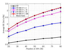
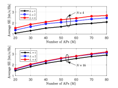
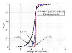
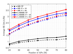
Figure 2 shows the average SE per UE as a function of the number of RIS elements NN. It is clear that in the considered setting, the per UE uplink SE increases with the number of RIS NN and AP MM. Moreover, the system performance of the RIS-aided CF system improves more significantly than that of the conventional CF system. In particular, when the number of elements NN is sufficiently large, for example, compared with N=64N=64, N=100N=100 only offers a marginal performance gain which reveals that it is not cost-effective to continuously increase the number of RIS elements in the CF system to achieve further system performance improvement.

Figure 3 shows the average SE per UE as a function of the number of AP MM and AP antennas LL with different NN. It is clear that increasing the number of AP antennas LL can improve the system performance as the increased number of spatial degrees of freedom facilitates more efficient beamforming. Moreover, it is interesting to find that when N=64N=64, the average SE gain of increasing the numbers of AP antennas is much smaller than that N=4N=4 due to channel hardening. This reveals that the number of AP antennas and RIS elements should be determined carefully to realize a cost-effective system.

Figure 4 shows the CDF of average SE per UE under the spatial correlations of AP antennas and RIS elements. We consider dV=dH=1/8λ,1/4λ,1/2λ{d_{V}}={d_{H}}={1\mathord{\left/{\vphantom{18}}\right.\kern-1.2pt}8}\lambda,{1\mathord{\left/{\vphantom{14}}\right.\kern-1.2pt}4}\lambda,{1\mathord{\left/{\vphantom{12}}\right.\kern-1.2pt}2}\lambda denotes the spatial correlation of RIS elements. Let σφ=5{\sigma_{\varphi}}={5^{\circ}} and 𝐑mk=βmkNLoS𝐈N{{\bf{R}}_{mk}}=\beta_{mk}^{{\rm{NLoS}}}{{\bf{I}}_{N}} represent strong spatial correlation and uncorrelated scenarios of AP antennas, respectively. Note that the existence of correlation has a negative impact on the system performance, especially the correlation in RIS elements which lead to poor passive beamforming at the RIS. Moreover, when dV=1/8λ{d_{V}={1\mathord{\left/{\vphantom{18}}\right.\kern-1.2pt}8}\lambda}, the 95%95\%-likely performance is the best which is related to the characteristics of sinc function. Note that different from the conclusion which AP antenna spatial correlation is beneficial in [15], the RIS elements correlation in the aggregated channel affects the AP antennas correlation, resulting in both negative impacts.

Figure 5 shows the average SE per UE as a function of the number of APs MM for different NN for the L-MMSE and the MR combining based on the MMSE estimation. For the L-MMSE combining scheme, the average SE can obtain 10.69%10.69\% and 7.15%7.15\% of gain on that of the MR at M=80M=80 for N=64N=64 and N=16N=16, respectively. It is clear that the performance gap between L-MMSE and MR combining becomes larger with the increase of NN since L-MMSE combining can fully exploit all the elements on RIS to suppress interference. Yet, the performance gain of the L-MMSE comes at the expense of involved computation as indicated in (11).

V Conclusions

In this paper, we study the uplink SE of a spatially correlated RIS-aided CF mMIMO system over spatially correlated channels with multi-antenna APs. For the MMSE channel estimation, we analyzed the uplink SE for the APs adopting the MR/L-MMSE combining and obtained the closed-form SE expressions for the MR combining. It is clear that increasing the number of RIS elements and AP antennas is beneficial to the system performance. Moreover, the spatial correlations of RIS elements and AP antennas both impose a negative impact on the uplink SE and the elements with half-wavelength spacing at the RIS obtain the best performance. Finally, the L-MMSE combining performs better than the MR combining with a large number of RIS elements. In future work, we will consider the power control and the beamforming design to enable the implementation of RIS-aided CF mMIMO networks.

Appendix A Proof of Theorem 1

This appendix calculates the covariance matrix in (5). To start with, we express

𝔼{𝐨~mk𝐨~mkH}=𝐑mk+𝐇¯mH𝚽𝐑~k𝚽H𝐇¯m\displaystyle\mathbb{E}\!\!\left\{\!{{{{{\bf{\tilde{o}}}}_{mk}}{{{\bf{\tilde{o}}}}^{H}_{mk}}}}\!\right\}={{\bf{R}}_{mk}}+{\bf{\bar{H}}}_{m}^{H}{\bf{\Phi}}{{{\bf{\tilde{R}}}}_{k}}{{\bf{\Phi}}^{H}}{{{\bf{\bar{H}}}}_{m}}
+𝔼{𝐇~mH𝚽𝐳¯k𝐳¯kH𝚽H𝐇~m}𝐐mk1+𝔼{𝐇~mH𝚽𝐳~k𝐳~kH𝚽H𝐇~m}𝐐mk2.\displaystyle+\!\!\underbrace{\mathbb{E}\!\left\{\!{{\bf{\tilde{H}}}_{m}^{H}{\bf{\Phi}}{{{\bf{\bar{z}}}}_{k}}{\bf{\bar{z}}}_{k}^{H}{{\bf{\Phi}}^{H}}{{{\bf{\tilde{H}}}}_{m}}}\!\right\}}_{{\bf{Q}}^{1}_{mk}}\!\!+\!\underbrace{\mathbb{E}\!\left\{\!{{\bf{\tilde{H}}}_{m}^{H}{\bf{\Phi}}{{{\bf{\tilde{z}}}}_{k}}{\bf{\tilde{z}}}_{k}^{H}{{\bf{\Phi}}^{H}}{{{\bf{\tilde{H}}}}_{m}}}\!\right\}}_{{\bf{Q}}^{2}_{mk}}. (27)

To calculate 𝐐mk1{{\bf{Q}}^{1}_{mk}}, we let 𝐁k=𝚽𝐳¯k𝐳¯kH𝚽H{{\bf{B}}_{k}}\!\!=\!\!{\bf{\Phi}}{{{\bf{\bar{z}}}}_{k}}{\bf{\bar{z}}}_{k}^{H}{{\bf{\Phi}}^{H}}, ​𝐐mk1{{\bf{Q}}^{1}_{mk}} is derived as

𝐐mk1=𝔼{𝐇~1mH𝐁k𝐇~1m𝐇~1mH𝐁k𝐇~Lm𝐇~LmH𝐁k𝐇~1m𝐇~LmH𝐁k𝐇~Lm}.\displaystyle{{\bf{Q}}^{1}_{mk}}=\mathbb{E}\left\{{\begin{array}[]{*{20}{c}}{{\bf{\tilde{H}}}_{1m}^{H}{{\bf{B}}_{k}}{{{\bf{\tilde{H}}}}_{1m}}}&\!\!\cdots\!\!&{{\bf{\tilde{H}}}_{1m}^{H}{{\bf{B}}_{k}}{{{\bf{\tilde{H}}}}_{Lm}}}\\ \!\!\vdots\!\!&\!\!\ddots\!\!&\!\!\vdots\!\!\\ {{\bf{\tilde{H}}}_{Lm}^{H}{{\bf{B}}_{k}}{{{\bf{\tilde{H}}}}_{1m}}}&\!\!\cdots\!\!&{{\bf{\tilde{H}}}_{Lm}^{H}{{\bf{B}}_{k}}{{{\bf{\tilde{H}}}}_{Lm}}}\end{array}}\right\}. (31)

For each element in 𝐐mk1{{\bf{Q}}^{1}_{mk}}, we can obtain 𝔼{𝐇~lmH𝐁k𝐇~lm}=(a)tr(𝐁k[𝐑~m](lNN+1lN,lNN+1lN))\mathbb{E}\!\left\{\!{{\bf{\tilde{H}}}_{lm}^{H}{{\bf{B}}_{k}}{{{\bf{\tilde{H}}}}_{l^{\prime}m}}}\!\right\}\!{\buildrel(a)\over{=}}{\rm{tr}}\!\!\left(\!\!{{{\bf{B}}_{k}}{{\left[\!{{{{\bf{\tilde{R}}}}_{m}}}\!\right]}_{\left({lN-N+1\sim lN,l^{\prime}N-N+1\sim l^{\prime}N}\right)}}}\!\right), where (a) follows by applying the trace of product property tr(𝐗𝐘)=tr(𝐘𝐗){\rm{tr}}\left({{\bf{XY}}}\right)={\rm{tr}}\left({{\bf{YX}}}\right) for some given size-matched matrices 𝐗{\bf{X}} and 𝐘{\bf{Y}}. We calculate llll^{\prime}-th element [𝐐mk2]ll=tr(𝚽𝐑~k𝚽H[𝐑~m](lNN+1lN,lNN+1lN)){\left[{{\bf{Q}}_{mk}^{2}}\right]_{ll^{\prime}}}={\rm{tr}}\left({{\bf{\Phi}}{{{\bf{\tilde{R}}}}_{k}}{{\bf{\Phi}}^{H}}{{\left[{{{{\bf{\tilde{R}}}}_{m}}}\right]}_{\left({lN-N+1\sim lN,l^{\prime}N-N+1\sim l^{\prime}N}\right)}}}\right) by applying the same method as above.

Appendix B Proof of Theorem 2

The expectations in (14) are calculated here. We begin with the molecular term as

𝔼{𝐮kk}=𝔼{[𝐨^1kH𝐨^1k,,𝐨^MkH𝐨^Mk]T}\displaystyle\mathbb{E}\left\{{{{\bf{u}}_{kk}}}\right\}=\mathbb{E}\left\{{{{\left[{{\bf{\hat{o}}}_{1k}^{H}{{{\bf{\hat{o}}}}_{1k}},\cdots,{\bf{\hat{o}}}_{Mk}^{H}{{{\bf{\hat{o}}}}_{Mk}}}\right]}^{T}}}\right\}
=[tr(p^kτp𝛀1k)+𝐨¯1k2,,tr(p^kτp𝛀Mk)+𝐨¯Mk2]T.\displaystyle=\!\!{\left[{{\rm{tr}}\left({{\hat{p}_{k}}{\tau_{p}}{{\bf{\Omega}}_{1k}}}\right)\!\!+\!\!{{\left\|{{{{\bf{\bar{o}}}}_{1k}}}\right\|}^{2}}\!,\!\cdots\!,\!{\rm{tr}}\left({{\hat{p}_{k}}{\tau_{p}}{{\bf{\Omega}}_{Mk}}}\right)\!\!+\!\!{{\left\|{{{{\bf{\bar{o}}}}_{Mk}}}\right\|}^{2}}}\right]^{T}}\!\!. (32)

Similarly, we compute the noise term as

𝐚kH𝐃k𝐚k=𝐚kHdiag(𝔼{𝐨^1k2},,𝔼{𝐨^Mk2})𝐚k\displaystyle{\bf{a}}_{k}^{H}{{\bf{D}}_{k}}{{\bf{a}}_{k}}={\bf{a}}_{k}^{H}{\rm{diag}}\left({\mathbb{E}\left\{{{{\left\|{{{{\bf{\hat{o}}}}_{1k}}}\right\|}^{2}}}\right\},\cdots,\mathbb{E}\left\{{{{\left\|{{{{\bf{\hat{o}}}}_{Mk}}}\right\|}^{2}}}\right\}}\right){{\bf{a}}_{k}}
=𝐚kHdiag(tr(p^kτp𝛀1k)+𝐨¯1k2,,tr(p^kτp𝛀Mk)+𝐨¯Mk2)𝐚k\displaystyle\!=\!\!{\bf{a}}_{k}^{H}\!{\rm{diag}}\!\left(\!{{\rm{tr}}\!\left({{\hat{p}_{k}}{\tau_{p}}{{\bf{\Omega}}_{1k}}}\!\right)\!\!+\!\!{{\left\|{{{{\bf{\bar{o}}}}_{1k}}}\right\|}^{2}}\!\!,\!\cdots\!\!,{\rm{tr}}\!\left({{\hat{p}_{k}}{\tau_{p}}{{\bf{\Omega}}_{Mk}}}\right)\!\!+\!\!{{\left\|{{{{\bf{\bar{o}}}}_{Mk}}}\right\|}^{2}}}\!\right)\!{{\bf{a}}_{k}}
=𝐀kHdiag(z1k,,zMk)𝐀k.\displaystyle={\bf{A}}_{k}^{H}{\rm{diag}}\left({{z_{1k}},\cdots,{z_{Mk}}}\right){{\bf{A}}_{k}}. (33)

The interference term in the denominator of (14) is

𝔼{|m=1Mamk𝐨^mkH𝐨mi|2}\displaystyle\mathbb{E}\left\{{{{\left|{\sum\limits_{m=1}^{M}{a_{mk}{\bf{\hat{o}}}_{mk}^{H}{{\bf{o}}_{mi}}}}\right|}^{2}}}\right\}
=m=1Mn=1Mamkank𝔼{(𝐨^mkH𝐨mi)H(𝐨^nkH𝐨ni)},\displaystyle=\sum\limits_{m=1}^{M}{\sum\limits_{n=1}^{M}{{a_{mk}}a_{nk}^{*}}}\mathbb{E}\left\{{{{\left({{\bf{\hat{o}}}_{mk}^{H}{{\bf{o}}_{mi}}}\right)}^{H}}\left({{\bf{\hat{o}}}_{nk}^{H}{{\bf{o}}_{ni}}}\right)}\right\}, (34)

where 𝔼{(𝐨^mkH𝐨mi)H(𝐨^nkH𝐨ni)}\mathbb{E}\left\{{{{\left({{\bf{\hat{o}}}_{mk}^{H}{{\bf{o}}_{mi}}}\right)}^{H}}\left({{\bf{\hat{o}}}_{nk}^{H}{{\bf{o}}_{ni}}}\right)}\right\} is computed for all possible APs and UEs combinations. We utilize the independence of channel estimation at different APs. When mn,i𝒫km\neq n,i\notin{{\cal P}_{k}}, we obtain 𝔼{(𝐨^mkH𝐨mi)H(𝐨^nkH𝐨ni)}=0\mathbb{E}\left\{{{{\left({{\bf{\hat{o}}}_{mk}^{H}{{\bf{o}}_{mi}}}\right)}^{H}}\left({{\bf{\hat{o}}}_{nk}^{H}{{\bf{o}}_{ni}}}\right)}\right\}=0. For mn,i𝒫k\{k}m\neq n,i\in{{\cal P}_{k}}\backslash\left\{k\right\}, we derive 𝔼{(𝐨^mkH𝐨mi)H(𝐨^nkH𝐨ni)}=𝔼{𝐨^miH𝐨^mk}{𝐨^nkH𝐨^ni}\mathbb{E}\left\{{{{\left({{\bf{\hat{o}}}_{mk}^{H}{{\bf{o}}_{mi}}}\right)}^{H}}\left({{\bf{\hat{o}}}_{nk}^{H}{{\bf{o}}_{ni}}}\right)}\right\}=\mathbb{E}\left\{{{\bf{\hat{o}}}_{mi}^{H}{{{\bf{\hat{o}}}}_{mk}}}\right\}\left\{{{\bf{\hat{o}}}_{nk}^{H}{{{\bf{\hat{o}}}}_{ni}}}\right\}, where

𝔼{𝐨^miH𝐨^mk}=p^kp^iτptr(𝐑mko𝚿mk1𝐑mio),\displaystyle\mathbb{E}\left\{{{\bf{\hat{o}}}_{mi}^{H}{{{\bf{\hat{o}}}}_{mk}}}\right\}=\sqrt{{{\hat{p}}_{k}}{{\hat{p}}_{i}}}{\tau_{p}}{\rm{tr}}\left({{\bf{R}}_{mk}^{o}{\bf{\Psi}}_{mk}^{-1}{\bf{R}}_{mi}^{o}}\right), (35)

since 𝔼{𝐨¯mkH𝐨¯miejφmkejφmi}=0\mathbb{E}\left\{{{{{\bf{\bar{o}}}}^{H}_{mk}}{{{\bf{\bar{o}}}}_{mi}}{e^{-j{\varphi_{mk}}}}{e^{j{\varphi_{mi}}}}}\right\}=0 and 𝔼{p^kτp(𝐑mko𝚿mk1(𝐲mkp𝐲¯mkp))H𝐨¯miejφmi}=0\mathbb{E}\left\{{\sqrt{{\hat{p}_{k}}{\tau_{p}}}\left({\bf{R}}_{mk}^{o}{\bf{\Psi}}_{mk}^{-1}\left({{\bf{y}}_{mk}^{p}-{\bf{\bar{y}}}_{mk}^{p}}\right)\right)^{H}{{{\bf{\bar{o}}}}_{mi}}{e^{j{\varphi_{mi}}}}}\right\}=0. We repeat the same calculation for AP nn and obtain

𝔼{(𝐨^mkH𝐨mi)H(𝐨^nkH𝐨ni)}\displaystyle\mathbb{E}\left\{{{{\left({{\bf{\hat{o}}}_{mk}^{H}{{\bf{o}}_{mi}}}\right)}^{H}}\left({{\bf{\hat{o}}}_{nk}^{H}{{\bf{o}}_{ni}}}\right)}\right\}
=p^kp^iτp2tr(𝐑mko𝚿mk1𝐑mio)tr(𝐑nio𝚿nk1𝐑nko).\displaystyle={{\hat{p}}_{k}}{{\hat{p}}_{i}}\tau_{p}^{2}{\rm{tr}}\left({{\bf{R}}_{mk}^{o}{\bf{\Psi}}_{mk}^{-1}{\bf{R}}_{mi}^{o}}\right){\rm{tr}}\left({{\bf{R}}_{ni}^{o}{\bf{\Psi}}_{nk}^{-1}{\bf{R}}_{nk}^{o}}\right). (36)

For another case mn,i=km\neq n,i=k, we obtain

𝔼{(𝐨^mkH𝐨mi)H(𝐨^nkH𝐨ni)}\displaystyle\mathbb{E}\left\{{{{\left({{\bf{\hat{o}}}_{mk}^{H}{{\bf{o}}_{mi}}}\right)}^{H}}\left({{\bf{\hat{o}}}_{nk}^{H}{{\bf{o}}_{ni}}}\right)}\right\}
=p^k2τp2tr(𝛀mk)tr(𝛀nk)+tr(𝐨¯mk𝐨¯mkH)tr(𝐨¯nk𝐨¯nkH)\displaystyle=\hat{p}_{k}^{2}\tau_{p}^{2}{\rm{tr}}\left({{{\bf{\Omega}}_{mk}}}\right){\rm{tr}}\left({{{\bf{\Omega}}_{nk}}}\right)+{\rm{tr}}\left({{{{\bf{\bar{o}}}}_{mk}}{\bf{\bar{o}}}_{mk}^{H}}\right){\rm{tr}}\left({{{{\bf{\bar{o}}}}_{nk}}{\bf{\bar{o}}}_{nk}^{H}}\right)
+p^kτptr(𝛀nk)tr(𝐨¯mk𝐨¯mkH)+p^kτptr(𝛀mk)tr(𝐨¯nk𝐨¯nkH).\displaystyle+{{\hat{p}}_{k}}{\tau_{p}}{\rm{tr}}\left({{{\bf{\Omega}}_{nk}}}\right){\rm{tr}}\left({{{{\bf{\bar{o}}}}_{mk}}{\bf{\bar{o}}}_{mk}^{H}}\right)+{{\hat{p}}_{k}}{\tau_{p}}{\rm{tr}}\left({{{\bf{\Omega}}_{mk}}}\right){\rm{tr}}\left({{{{\bf{\bar{o}}}}_{nk}}{\bf{\bar{o}}}_{nk}^{H}}\right). (37)

Similarly for m=n,i=km=n,i=k, we utilize the same method as in [13] that yields

𝔼{|𝐨^mkH𝐨mk|2}=p^k2τp2|tr(𝛀mk)|2+p^kτptr(𝛀mk𝐑mko)\displaystyle\mathbb{E}\left\{{{{\left|{{\bf{\hat{o}}}_{mk}^{H}{{\bf{o}}_{mk}}}\right|}^{2}}}\right\}=\hat{p}_{k}^{2}\tau_{p}^{2}{\left|{{\rm{tr}}\left({{{\bf{\Omega}}_{mk}}}\right)}\right|^{2}}+{{\hat{p}}_{k}}{\tau_{p}}{\rm{tr}}\left({{{\bf{\Omega}}_{mk}}{\bf{R}}_{mk}^{o}}\right)
+𝐨¯mkH𝐑mko𝐨¯mk+p^kτp𝐨¯mkH𝛀mk𝐨¯mk\displaystyle+{\bf{\bar{o}}}_{mk}^{H}{\bf{R}}_{mk}^{o}{{{\bf{\bar{o}}}}_{mk}}+{{\hat{p}}_{k}}{\tau_{p}}{\bf{\bar{o}}}_{mk}^{H}{{\bf{\Omega}}_{mk}}{{{\bf{\bar{o}}}}_{mk}}
+2p^kτptr(𝛀mk)𝐨¯mkH𝐨¯mk+tr(𝐨¯mk𝐨¯mkH)2.\displaystyle+2{{\hat{p}}_{k}}{\tau_{p}}{\rm{tr}}\left({{{\bf{\Omega}}_{mk}}}\right){\bf{\bar{o}}}_{mk}^{H}{{{\bf{\bar{o}}}}_{mk}}+{\rm{tr}}{\left({{{{\bf{\bar{o}}}}_{mk}}{\bf{\bar{o}}}_{mk}^{H}}\right)^{2}}. (38)

Then, for the case m=n,i𝒫km=n,i\notin{{\cal P}_{k}}, we obtain

𝔼{|𝐨^mkH𝐨mi|2}=p^kτptr(𝐑mio𝛀mk)\displaystyle\mathbb{E}\left\{{{{\left|{{\bf{\hat{o}}}_{mk}^{H}{{\bf{o}}_{mi}}}\right|}^{2}}}\right\}={\hat{p}_{k}}{\tau_{p}}{\rm{tr}}\left({{\bf{R}}_{mi}^{o}{{\bf{\Omega}}_{mk}}}\right)
+𝐨¯mkH𝐑mio𝐨¯mk+p^kτp𝐨¯miH𝛀mk𝐨¯mi+|𝐨¯mkH𝐨¯mi|2.\displaystyle+{\bf{\bar{o}}}_{mk}^{H}{\bf{R}}_{mi}^{o}{{{\bf{\bar{o}}}}_{mk}}+{\hat{p}_{k}}{\tau_{p}}{\bf{\bar{o}}}_{mi}^{H}{{\bf{\Omega}}_{mk}}{{{\bf{\bar{o}}}}_{mi}}+{\left|{{\bf{\bar{o}}}_{mk}^{H}{{{\bf{\bar{o}}}}_{mi}}}\right|^{2}}. (39)

For m=n,i𝒫k\{k}m=n,i\in{{\cal P}_{k}}\backslash\left\{k\right\}, we obtain

𝔼{|𝐨^mkH𝐨mi|2}=p^kτptr(𝛀mk𝐑mio)+tr(𝐨¯mk𝐨¯mkH𝐑mio)\displaystyle\mathbb{E}\left\{{{{\left|{{\bf{\hat{o}}}_{mk}^{H}{{\bf{o}}_{mi}}}\right|}^{2}}}\right\}={{\hat{p}}_{k}}{\tau_{p}}{\rm{tr}}\left({{{\bf{\Omega}}_{mk}}{\bf{R}}_{mi}^{o}}\right){\rm{+tr}}\left({{{{\bf{\bar{o}}}}_{mk}}{\bf{\bar{o}}}_{mk}^{H}{\bf{R}}_{mi}^{o}}\right)
+|𝐨¯mkH𝐨¯mi|2+p^kp^iτp2|tr(𝐑mko𝚿mk1𝐑mko)|2.\displaystyle+{\left|{{\bf{\bar{o}}}_{mk}^{H}{{{\bf{\bar{o}}}}_{mi}}}\right|^{2}}+{{\hat{p}}_{k}}{{\hat{p}}_{i}}\tau_{p}^{2}{\left|{{\rm{tr}}\left({{\bf{R}}_{mk}^{o}{\bf{\Psi}}_{mk}^{-1}{\bf{R}}_{mk}^{o}}\right)}\right|^{2}}. (40)

Finally, we can derive the expectation of (14).

References

  • [1] J. Zhang, E. Björnson, M. Matthaiou, D. W. K. Ng, H. Yang, and D. J. Love, “Prospective multiple antenna technologies for beyond 5G,” IEEE J. Sel. Areas Commun., vol. 38, no. 8, pp. 1637–1660, Aug. 2020.
  • [2] H. Q. Ngo, A. Ashikhmin, H. Yang, E. G. Larsson, and T. L. Marzetta, “Cell-free massive MIMO versus small cells,” IEEE Trans. Wireless Commun., vol. 16, no. 3, pp. 1834–1850, Mar. 2017.
  • [3] E. Björnson and L. Sanguinetti, “Making cell-free massive MIMO competitive with MMSE processing and centralized implementation,” IEEE Trans. Wireless Commun., vol. 19, no. 1, pp. 77–90, Jan. 2019.
  • [4] Q. Wu and R. Zhang, “Intelligent reflecting surface enhanced wireless network via joint active and passive beamforming,” IEEE Trans. Wireless Commun., vol. 18, no. 11, pp. 5394–5409, Nov. 2019.
  • [5] E. Shi, J. Zhang, S. Chen, J. Zheng, Y. Zhang, D. W. Kwan Ng, and B. Ai, “Wireless energy transfer in RIS-aided cell-free massive MIMO systems: Opportunities and challenges,” IEEE Commun. Mag., vol. 60, no. 3, pp. 26–32, Mar. 2022.
  • [6] J. Zhang, H. Liu, Q. Wu, Y. Jin, Y. Chen, B. Ai, S. Jin, and T. J. Cui, “Ris-aided next-generation high-speed train communications: Challenges, solutions, and future directions,” IEEE Wireless Commun., vol. 28, no. 6, pp. 145–151, Dec. 2021.
  • [7] Y. Zhang, B. Di, H. Zhang, J. Lin, Y. Li, and L. Song, “Reconfigurable intelligent surface aided cell-free MIMO communications,” IEEE Wireless Commun. Lett., vol. 10, no. 4, pp. 775–779, Apr. 2021.
  • [8] M. Bashar, K. Cumanan, A. G. Burr, P. Xiao, and M. Di Renzo, “On the performance of reconfigurable intelligent surface-aided cell-free massive MIMO uplink,” in Proc. IEEE GLOBECOM, 2020, pp. 1–6.
  • [9] E. Björnson and L. Sanguinetti, “Rayleigh fading modeling and channel hardening for reconfigurable intelligent surfaces,” IEEE Wireless Commun. Lett., vol. 10, no. 4, pp. 830–834, Apr. 2020.
  • [10] T. Van Chien, H. Q. Ngo, S. Chatzinotas, M. Di Renzo, and B. Ottersten, “Reconfigurable intelligent surface-assisted cell-free massive MIMO systems over spatially-correlated channels,” IEEE Trans. Wireless Commun., vol. 21, no. 7, pp. 5106–5128, Jul. 2022.
  • [11] J. Zhang, J. Zhang, D. W. K. Ng, S. Jin, and B. Ai, “Improving sum-rate of cell-free massive MIMO with expanded compute-and-forward,” IEEE Trans. Signal Process., vol. 70, pp. 202–215, 2021.
  • [12] Z. Wang, J. Zhang, B. Ai, C. Yuen, and M. Debbah, “Uplink performance of cell-free massive MIMO with multi-antenna users over jointly-correlated Rayleigh fading channels,” IEEE Trans. Wireless Commun., to appear, 2022.
  • [13] Ö. Özdogan, E. Björnson, and J. Zhang, “Performance of cell-free massive MIMO with Rician fading and phase shifts,” IEEE Trans. Wireless Commun., vol. 18, no. 11, pp. 5299–5315, Nov. 2019.
  • [14] J. Zheng, J. Zhang, E. Björnson, Z. Li, and B. Ai, “Cell-free massive MIMO-OFDM for high-speed train communications,” IEEE J. Sel. Areas Commun., to appear, 2022.
  • [15] Z. Wang, J. Zhang, E. Björnson, and B. Ai, “Uplink performance of cell-free massive MIMO over spatially correlated rician fading channels,” IEEE Commun. Lett., vol. 25, no. 4, pp. 1348–1352, Apr. 2020.
  • [16] J. Zhang, J. Zhang, E. Björnson, and B. Ai, “Local partial zero-forcing combining for cell-free massive MIMO systems,” IEEE Trans. Commun., vol. 69, no. 12, pp. 8459–8473, Dec. 2021.
  • [17] E. Björnson, J. Hoydis, and L. Sanguinetti, “Massive mimo networks: Spectral, energy, and hardware efficiency,” Foundations and Trends in Signal Processing, vol. 11, no. 3-4, pp. 154–655, 2017.