Vision-Based Autonomous MM-Wave Reflector Using ArUco-Driven Angle-of-Arrival Estimation
Abstract
Reliable millimeter-wave (mmWave) communication in non-line-of-sight (NLoS) conditions remains a major challenge for both military and civilian operations, especially in urban or infrastructure-limited environments. This paper presents a vision-aided autonomous reflector system designed to enhance mmWave link performance by dynamically steering signal reflections using a motorized metallic plate. The proposed system leverages a monocular camera to detect ArUco markers on allied transmitter and receiver nodes, estimate their angles of arrival, and align the reflector in real time for optimal signal redirection. This approach enables selective beam coverage by serving only authenticated targets with visible markers and reduces the risk of unintended signal exposure. The designed prototype, built on a Raspberry Pi 4 and low-power hardware, operates autonomously without reliance on external infrastructure or GPS. Experimental results at 60 GHz demonstrate a 23 dB average gain in received signal strength and an 0.89 probability of maintaining signal reception above a target threshold of -65 dB in an indoor environment, far exceeding the static and no-reflector baselines. These results demonstrate the system’s potential for resilient and adaptive mmWave connectivity in complex and dynamic environments.
Index Terms:
Millimeter-Wave Communications, Passive Reflector Steering, Vision-Aided Systems, Tactical Networking, Autonomous Platforms.I Introduction
Millimeter-wave (mmWave) and terahertz (THz) frequency bands offer transformative data rates and directional communication capabilities, making them highly attractive for next-generation military networks [1, 2, 3, 4]. However, their practical deployment is severely limited by their reliance on line-of-sight (LoS) conditions and their susceptibility to obstructions such as buildings, terrain, and moving vehicles, conditions commonly encountered in tactical operations. Ensuring reliable connectivity in such environments requires solutions that can rapidly adapt to changing environments and operate without heavy infrastructure or RF feedback overhead.
To overcome these challenges, a number of studies have investigated the use of Reconfigurable Intelligent Surfaces (RIS) for enhancing wireless propagation by enabling programmable control over reflected waves [5, 7, 8, 9, 6]. Nevertheless, RIS systems face significant challenges, including high complexity, power requirements, and reliance on intensive beam training and channel estimation. These constraints become increasingly prohibitive as user mobility increases and the number of potential reflectors grows.
Recent work [8, 9, 10, 11], proposed vision-aided systems as a scalable alternative, leveraging visual inputs such as RGB or depth images to eliminate dependence on real-time RF feedback. By correlating image data with spatial user location or directionality, these approaches achieve significant reductions in beam training overhead while maintaining near-optimal link quality. For instance, Ouyang et al. [8] implemented a 20×20 RIS panel with a stereo vision pipeline for real-time beam steering, while Jiang et al. [9] utilized monocular object detection to train neural networks for efficient beam index prediction. These efforts collectively demonstrate the feasibility of replacing conventional feedback links with low-cost vision sensors to drive RIS logic.
In parallel, several work investigated the use of passive reflectors to enhance mmWave coverage in NLoS environments [12, 13, 14]. Flat metallic reflectors and low-cost passive surfaces have been shown to significantly improve signal strength and coverage in constrained environments. While effective, these reflectors are static and cannot adapt to user movement or changing environmental conditions, making them unsuitable for mobile or dynamic environments.
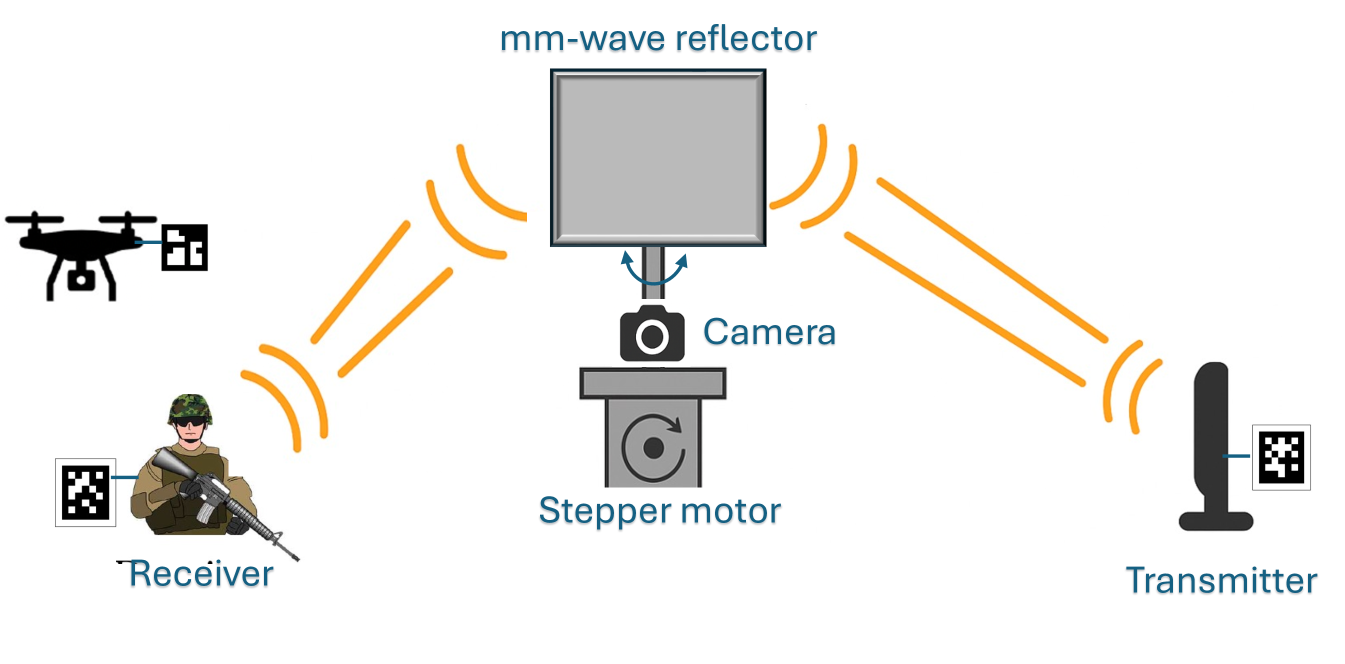
To bridge the gap between static passive reflectors and complex RIS panels, we propose a vision-aided autonomous reflector system that combines the low-power, infrastructure-free advantages of passive reflectors with the adaptability and intelligence of vision-based control. The proposed system, illustrated in Fig. 1, consists of a flat metallic plate mounted on a two-axis gimbal, steered by stepper motor and controlled via a Raspberry Pi 4. An onboard camera guides the system by detecting uniquely tagged transmitters and receivers using ArUco fiducial markers. Based on their relative positions, the system computes the optimal reflector orientation to enhance signal propagation through specular reflection.
In contrast to RF-based RIS architectures which require active electronic components, frequent channel estimation, and extensive beam training, our system operates entirely without RF feedback, thereby significantly reducing power consumption, system overhead, and implementation complexity. While conventional vision-aided RIS platforms often depend on high-resolution RGB or depth imagery and computationally intensive neural inference pipelines, our design leverages lightweight ArUco markers for real-time angle-of-arrival (AoA) estimation. This results in faster inference, reduced processing requirements, and increased robustness in visually degraded or rapidly changing environments.
Why ArUco: Unlike general-purpose object detection methods or QR codes, ArUco markers are specifically designed for real-time pose estimation and maintain reliable performance even under poor lighting, occlusion, and noise conditions. Recent advances such as DeepArUco++ have further enhanced detection robustness using convolutional neural networks, outperforming traditional methods in low-contrast and shadowed scenes [15]. Additionally, their square, high-contrast design enables precise six-degree-of-freedom (6-DoF) estimation with minimal computational overhead [16]. Furthermore, their use enables selective beam redirection in the sense that only users with valid markers are detected and served. This capability helps mitigate signal leakage and supports user-specific beam redirection, which is particularly beneficial in multiuser environments.
II System Model
We consider a millimeter-wave communication system in which a passive metallic reflector is deployed to enhance connectivity between a transmitter and a receiver, particularly in non-line-of-sight scenarios. The transmitter and receiver are tagged with known ArUco markers, and the direct line-of-sight path is assumed to be blocked, as illustrated in Fig. 1. In this setup, the reflector functions as an intelligent passive relay, redirecting the signal from the transmitter to the receiver via controlled alignment.
The system comprises a flat, perfectly conducting rectangular reflector mounted on a stepper motor and equipped with a monocular camera. This vision-aided setup allows the reflector to dynamically align itself toward both the transmitter and receiver by detecting their ArUco markers. When both markers are within the camera’s field of view, the reflector actively adjusts its orientation to maximize signal redirection through specular reflection. If either marker is not detected, the reflector operates in a static mode, behaving as a conventional passive surface. Although primarily designed for NLoS operation, the proposed system is also applicable in LoS scenarios to enhance link robustness or create beneficial multipath conditions through constructive interference.
II-A Power Model with Radar Cross Section
Under far-field and specular reflection conditions, the received power at the receiver due to reflection from the passive reflector is given by the bistatic radar equation [17, 18] as
| (1) |
where is the transmit power, and are the antenna gains at the transmitter and receiver, respectively, is the carrier wavelength, and are the distances from the transmitter to the reflector and from the reflector to the receiver, respectively, and is the bistatic radar cross section (RCS), which depends on the angles of incidence and reflection . For a perfectly conducting flat plate of area , the RCS under specular reflection and far-field assumptions can be approximated as [18]:
| (2) |
where is the bistatic angle subtended at the reflector between the transmitter and receiver. This formulation shows that the received power is highly sensitive to the orientation of the reflector. The maximum received power is achieved when , i.e., when the transmitter and receiver are symmetrically aligned about the surface normal of the reflector.
II-B Reflection Control Strategy
To optimize received power, the proposed system minimizes the bistatic angle by aligning the reflector such that the angles of incidence and reflection satisfy the condition . The onboard camera detects the ArUco markers of the transmitter and receiver, estimates their angles of arrival, and commands the stepper motor to orient the reflector for optimal beam alignment. This adaptive control strategy significantly improves the NLoS link quality in complex or obstructed environments.
III Vision-Based Reflector Orientation Using ArUco Markers
This section describes the vision-based method for orienting a passive reflector using detected ArUco markers. The approach utilizes image-space coordinates from a monocular camera and translates them into angular bearings to steer the reflector toward optimal alignment. Specifically, the camera captures visual information of the scene and identifies the (pixel) positions of ArUco markers affixed to the transmitter and receiver. These marker locations are used to estimate the corresponding AoAs. The reflector then reorients its surface to bisect the incident and reflected rays, thereby minimizing the bistatic angle and maximizing specular signal reflection.
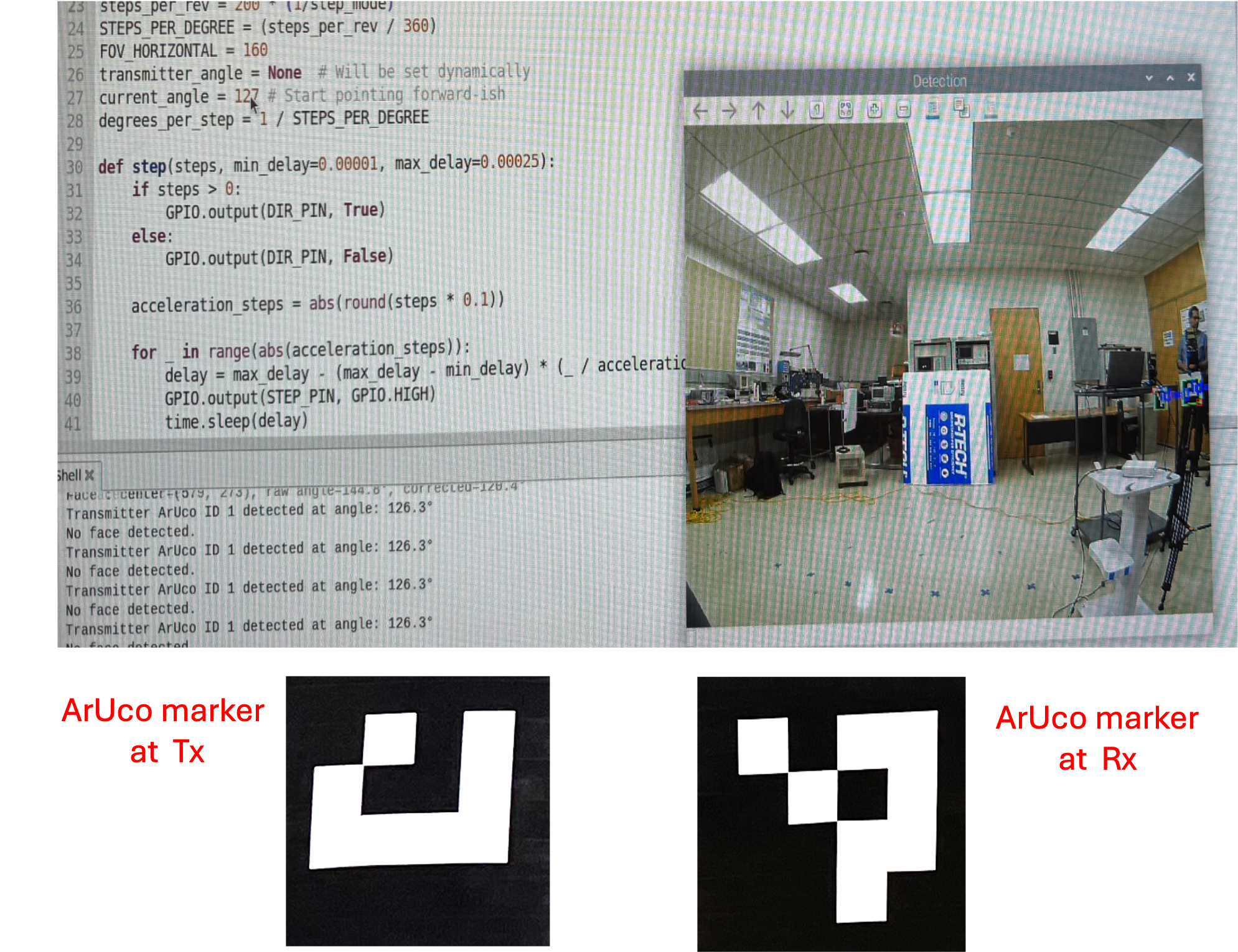
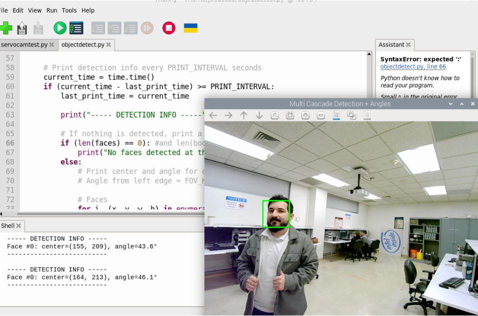
The detection of users incorporates two vision-based modalities, (i) OpenCV’s ArUco detector for marker-based pose estimation and identification [19], and (ii) an optional pre-trained OpenCV Haarcascade face detection model for optional user detection when markers are unavailable as shown in Figs. 2 and 3. This paper focuses on the marker-based path, which enables ID-based and deterministic control of the reflector orientation.
III-A AoA Estimation via Pixel-to-Angle Conversion
Let denote the horizontal pixel coordinate of a detected ArUco marker centroid, and let represent the camera’s frame width. Given a camera horizontal field of view (in degrees), the raw bearing angle is computed as:
| (3) |
This expression assumes a linear projection model, where the pixel coordinate is normalized by the frame width to produce a relative horizontal position ranging from 0 (left edge) to 1 (right edge) of the image. Multiplying by maps this normalized coordinate to an angular position across the field of view. The resulting represents the angle between the camera’s optical axis and the direction of the detected marker, measured from the left edge of the image frame.
To correct for radial distortion caused by the camera lens, the raw AoA estimate derived from the horizontal pixel location is adjusted using a nonlinear transformation. The correction is particularly important when using wide-angle or low-cost lenses, where the assumption of a linear pixel-to-angle relationship does not hold across the full field of view. Given a raw AoA estimate , the corrected AoA is computed as
| (4) |
where is the optical center of the camera’s field of view. This correction performs several operations. It first computes the angular offset of the detected marker from the optical center using ; then it applies a normalization factor of 4000 to constrain the input to the arctangent function within a numerically stable range. The arctangent introduces a nonlinear mapping that approximates the S-shaped distortion profile typical of barrel distortion, where angular deviation increases more slowly than pixel displacement near the image edges. This effect is evident in the image shown in Fig. 2. The output is then scaled by 43.5 and converted from radians to degrees using the factor . Finally, the result is re-centered by adding to maintain symmetry about the optical axis. Equation (4) provides a lightweight, empirically tuned alternative to polynomial radial distortion models, which require camera calibration to estimate parameters. While less precise than full calibration-based correction methods (e.g., using OpenCV’s intrinsic distortion coefficients), this approach is well-suited for real-time embedded systems where computational simplicity and rapid deployment are prioritized.
III-B Angle-to-Step Conversion
The stepper motor driving the reflector is characterized by full steps per revolution and an -way micro-stepping mode. The angular resolution per step is thus given by
| (5) |
Given the current reflector orientation and the desired orientation , the number of required motor steps is calculated as
| (6) |
III-C Reflector Orientation Calculation
To achieve optimal reflection based on Snell’s law, the reflector normal is set to bisect the incoming and outgoing angles. The desired reflector orientation angle is
| (7) |
where and are the estimated AoAs of the transmitter and receiver, respectively. The stepper motor then executes pulses in the appropriate direction to reach this orientation.
III-D Stepper Motor Calibration
As the stepper motor lacks absolute encoding, an initial calibration step is required. An operator temporarily disengages the motor coupling, manually aligns the reflector to a known reference orientation (e.g., ), re-engages the motor, and initializes . This one-time setup typically takes less than 5 seconds per deployment.
The above steps are summarized in Algorithm 1 and measurement scripts are available upon request in the GitHub repository (github.com/TacticalCircuits/signalreflection.git).
IV Prototype Architecture and
Experimental Setup
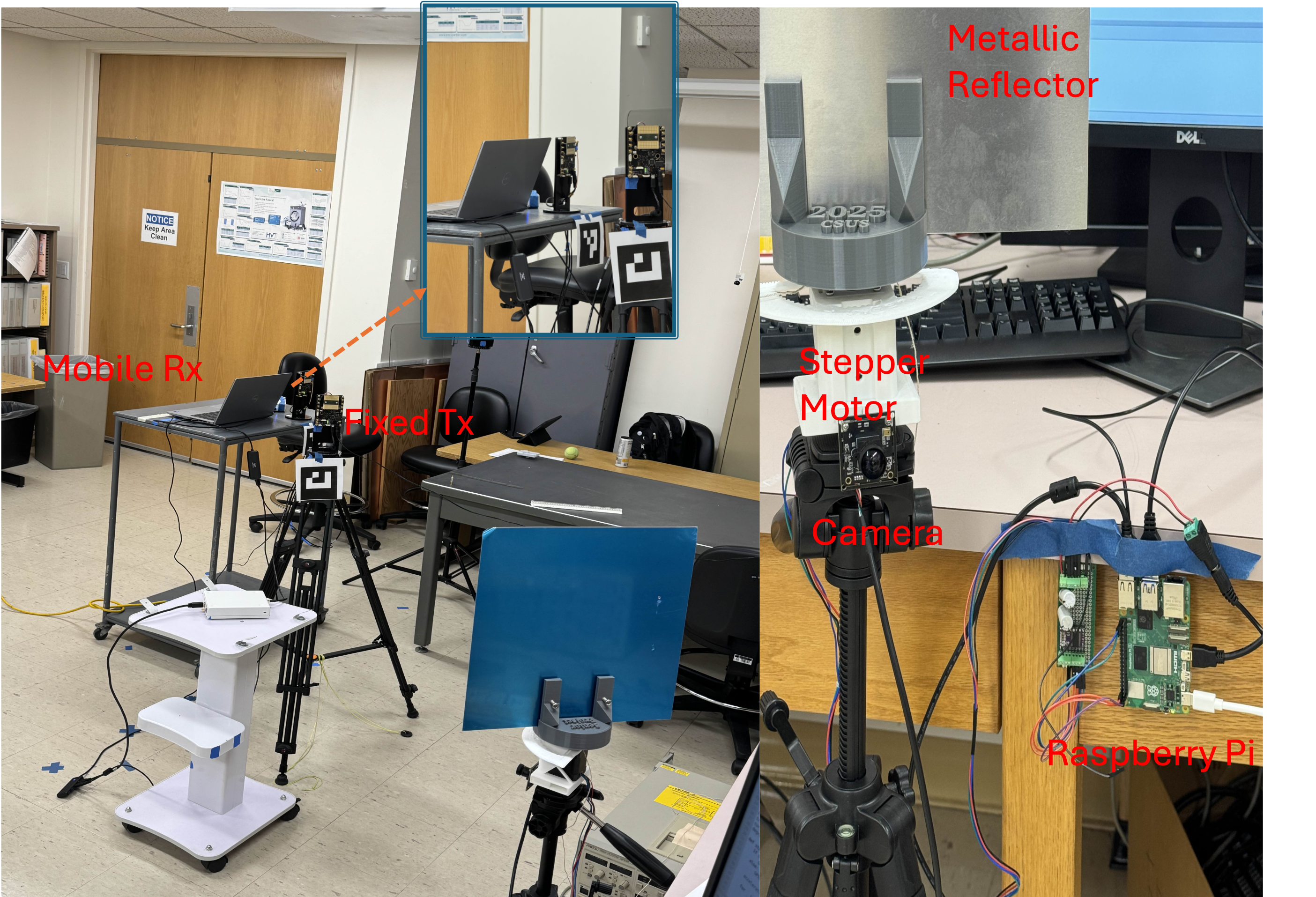
The architecture of the proposed vision-aided reflector prototype is illustrated in Fig. 4. The proof-of-concept system comprises a aluminum flat-plate reflector mounted on a two-axis Dynamixel gimbal. This gimbal is actuated by a 0.9∘ stepper motor configured to operate in 1/16 micro-stepping mode, providing an angular resolution of . The motor is driven by a DRV8824 breakout board, and the control pipeline is executed on a Raspberry Pi 4 running Ubuntu 22.04 with OpenCV 4.10.0. The camera used for visual detection is an Arducam OV9281 global-shutter module with a resolution of pixels and a horizontal field of view of . This camera continuously monitors the scene to detect ArUco markers placed on the transmitter and receiver, allowing the reflector to dynamically align itself for optimal mmWave signal redirection. Both the reflector alignment logic and stepper control are performed locally on the Raspberry Pi 4. The mmWave transceiver hardware consists of two 60 GHz Sivers phased-array modules integrated with NI-USRP baseband platforms. The transmitter, tagged with ArUco ID 1, is fixed and configured for directional transmission toward the reflector. The receiver, tagged with ArUco ID 0, is configured to operate in omnidirectional mode.
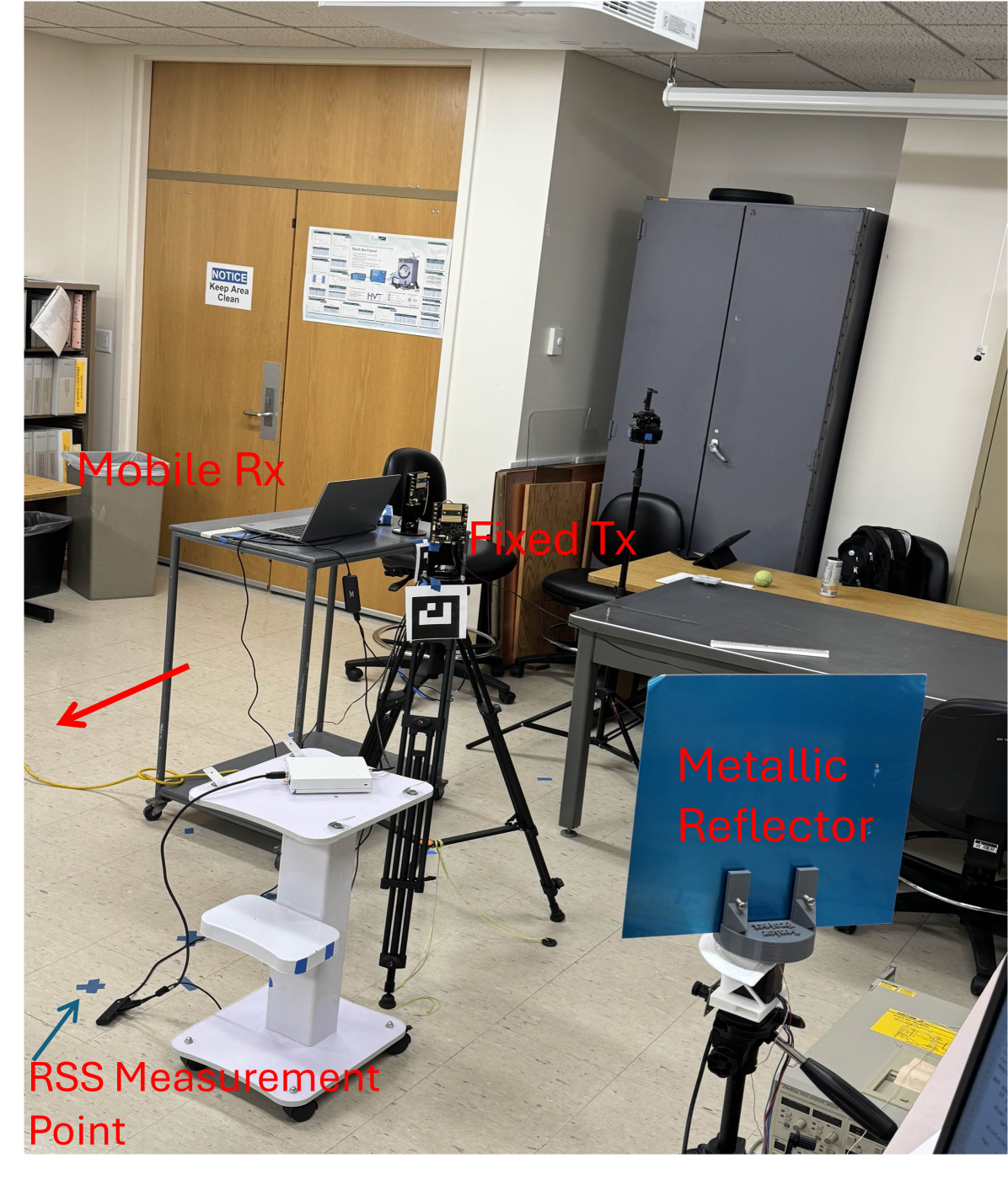
The experiment is conducted in an indoor lab environment under NLoS conditions between the transmitter and the receiver as shown in Fig. 5. The transmitter and receiver are initially located 5 ft and 6 ft from the reflector, respectively, each forming an angle of with respect to the reflector surface. The receiver is moved laterally to the left, as indicated by the red arrow in Fig. 5, with received signal strength (RSS) measurements taken at 0.5 ft intervals up to a total distance of 9.5 ft along the marked positions. The received signal strength, denoted by , is defined as the received power in arbitrary units (a. u.) normalized by a reference power P (a. u. ). The experiment is conducted under three different configurations to evaluate performance, namely, the proposed vision-aided reflector with dynamic steering, a static metallic reflector with fixed orientation [12], and a baseline scenario with no reflector deployed. For each configuration, the received signal strength is recorded at the receiver along the lateral sweep path.
The primary performance metric is the communication outage probability, defined as the probability that the RSS falls below a predefined threshold . Formally, this is expressed as . The goal of the proposed system is to minimize this outage probability by maintaining strong reflected links in NLoS scenarios.
V Experimental Results and Discussion
This section presents the experimental results comparing the proposed vision-guided reflector system against two baselines, namely a static metallic reflector configuration[12], and a no-reflector configuration. The evaluation focuses on RSS performance and link reliability across a defined measurement path in a NLoS indoor environment.
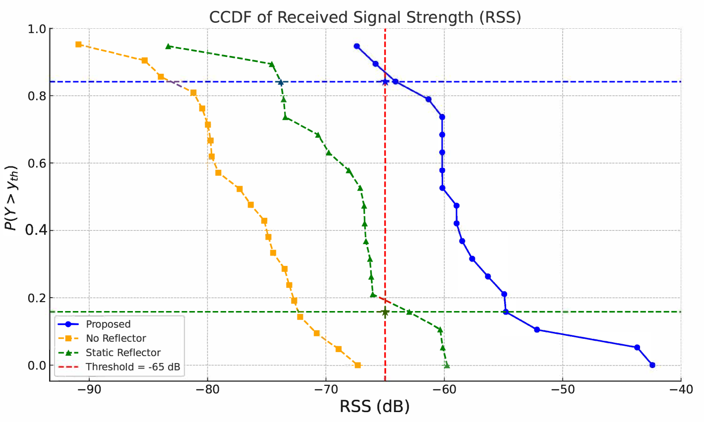
Fig. 6 shows the RSS complementary cumulative distribution function (CCDF) plotted against varying threshold levels . This plot illustrates the probability of maintaining RSS above a given threshold, i.e. . At dB, the proposed system achieves a success probability of 0.89, in contrast to 0.20 for the static reflector and 0.00 for the no-reflector case. This substantial improvement confirms that the vision-aided dynamic alignment significantly enhances link reliability and coverage.
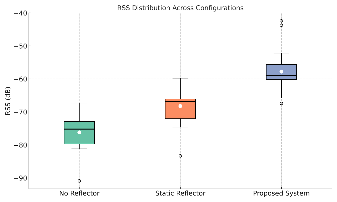
Further statistical insights are provided by the box plot in Fig. 7, which summarizes the RSS distribution for each configuration in terms of median, interquartile range (IQR), and outliers. The proposed system not only achieves the highest median RSS but also exhibits the smallest IQR of 4.55 dB, compared to 5.94 dB for the static reflector and 6.81 dB for the no-reflector case. These results indicate that the proposed vision aided reflector provides both stronger and more consistent signal strength across the test path, reducing variability and improving link predictability.
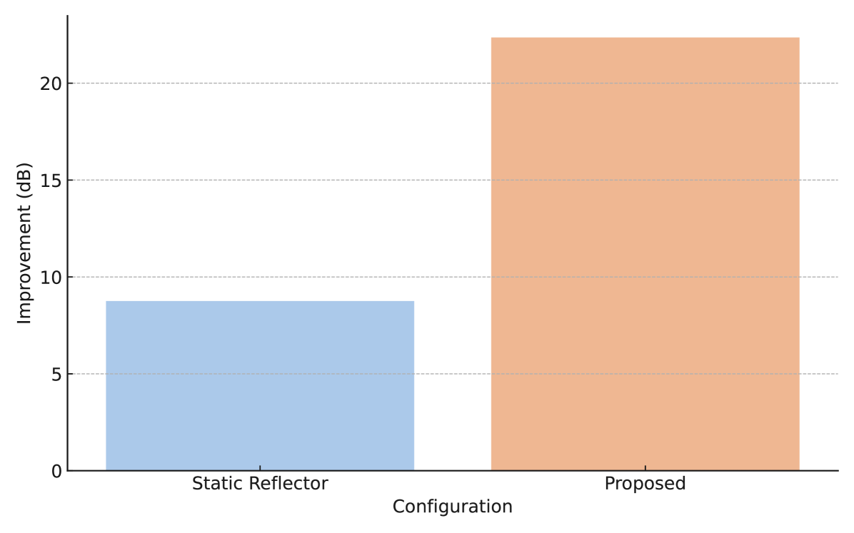
A bar graph comparing the average RSS gain achieved by the proposed system and the static reflector configuration, both relative to the baseline scenario (no reflector), is shown in Fig. 8. The proposed vision-guided reflector yields an average improvement of 23 dB, far outperforming the 7.6 dB gain observed with the static reflector. This confirms the effectiveness of the real-time orientation strategy in maximizing reflective gain and maintaining optimal reflector alignment as receiver positions change.
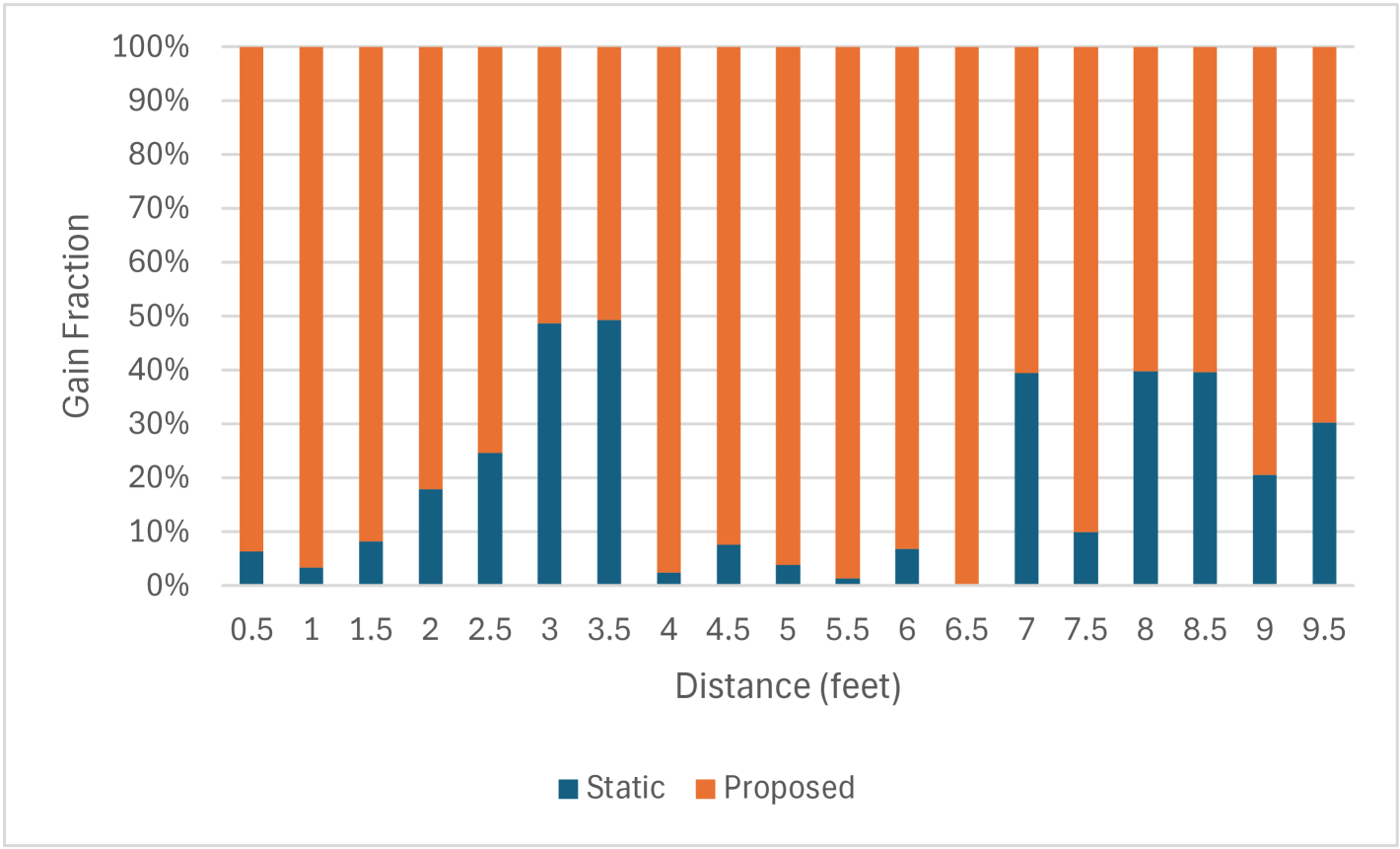
To gain further insights into the RSS gain provided by the proposed vision-based reflector compared to a static reflector, Fig. 9 presents a comparative analysis of RSS gain as a function of the receiver’s distance from the transmitter. This gain is computed relative to a no-reflector baseline and expressed as a percentage of the total combined gain between the two reflector configurations. Fig. 9 shows that at distances of 3 and 3.5 feet, both reflector configurations yield an equivalent 50% contribution to the overall gain, suggesting these locations correspond to the optimal alignment points for the static reflector. Between 7 and 9.5 feet, the gain contributions from the static reflector approach those of the proposed system, likely due to favorable secondary multipath reflections within the room. Despite this localized improvement, the vision-guided reflector consistently achieves stronger and more dominant gain performance, reaching close to 100% gain contribution at several positions. These results highlight the advantage of real-time camera-guided reflector orientation for enhancing mmWave signal coverage.
VI Conclusion
This paper proposed a vision-guided passive reflector prototype to enhance mmWave communications in dynamic NLoS environments. The proposed system uses real-time angle estimation and ArUco marker detection to autonomously align a gimbal-mounted reflector towards verified endpoints. Experimental indoor results at 60 GHz show a 23 dB average gain in received signal strength and an increase in link availability from 20% to 89% compared to a static reflector, with reduced signal variability. The proposed compact, low-power, and infrastructure-free reflector design enables robust, secure, and rapidly deployable communications for mobile units, unmanned platforms, and dismounted teams in complex and dynamic environments. Future work will explore mounting the reflector system on drones to extend NLoS communication coverage, particularly in tactically constrained or hard-to-reach regions.
Acknowledgment
This material is based on work supported by the National Science Foundation under grant No. NSF-2243089.
References
- [1] W. Jiang, B. Shen, L. Zhang, Y. Zeng, M. Shafi, and T. S. Rappaport, “Terahertz communications and sensing for 6G and beyond: A comprehensive review,” IEEE Communications Surveys & Tutorials, vol. 26, no. 4, pp. 2326–2381, Fourthquarter 2024.
- [2] J. F. Harvey, M. B. Steer, and T. S. Rappaport, “Exploiting high millimeter wave bands for military communications, applications, and design,” IEEE Access, vol. 7, pp. 52350–52359, 2019.
- [3] D. Kim, M. R. Castellanos, and R. W. Heath, “Joint Beam Management and Relay Selection Using Deep Reinforcement Learning for MmWave UAV Relay Networks,” in MILCOM 2022 - 2022 IEEE Military Communications Conference (MILCOM), Rockville, MD, USA, 2022, pp. 895–900.
- [4] A. Vaccari, M. Z. Win, and A. Conti, “Tracking and Identification of Targets via mmWave MIMO Radar,” in MILCOM 2024 - 2024 IEEE Military Communications Conference (MILCOM), Washington, DC, USA, 2024, pp. 336–341.
- [5] Y. Liu et al., “Reconfigurable intelligent surfaces: Principles and opportunities,“IEEE Commun. Surveys Tuts., vol. 23, no. 3, pp. 1546–1577, 2021.
- [6] X. Pei et al., “RIS-aided Wireless Communications: Prototyping, Adaptive Beamforming, and Indoor/Outdoor Field Trials,” IEEE Trans. Commun., vol. 69, no. 12, pp. 8627–8640, Dec. 2021.
- [7] M. A. ElMossallamy et al., “Reconfigurable intelligent surfaces for wireless communications: Principles, challenges, and opportunities,” IEEE Trans. Cogn. Commun. Netw., vol. 6, no. 3, pp. 990–1002, 2020.
- [8] M. Ouyang, Y. Wang, F. Gao, S. Zhang, P. Li, and J. Ren, “Computer Vision-Aided Reconfigurable Intelligent Surface-Based Beam Tracking: Prototyping and Experimental Results,” IEEE Transactions on Wireless Communications, vol. 22, no. 12, pp. 8681–8693, Dec. 2023.
- [9] S. Jiang, A. Hindy, and A. Alkhateeb, “Camera Aided Reconfigurable Intelligent Surfaces: Computer Vision Based Fast Beam Selection,” in Proceedings of the IEEE International Conference on Communications (ICC), Rome, Italy, May 2023, pp. 2921–2926.
- [10] G. Charan et al., “Vision-Aided 6G Wireless Communications: Blockage Prediction and Proactive Handoff,” IEEE Trans. Veh. Technol., vol. 70, no. 10, pp. 10193-10208, 2021.
- [11] B. Salehi et al., “Machine learning on camera images for fast mmwave beamforming,” in Proc. IEEE MASS, 2020, pp. 338–346.
- [12] W. Khawaja, O. Ozdemir, Y. Yapici, F. Erden, M. Ezuma, and I. Guvenc, “Coverage enhancement for NLOS mmWave links using passive reflectors,” IEEE Open Journal of the Communications Society, vol. 1, pp. 263–281, 2020.
- [13] W. Khawaja, O. Ozdemir, F. Erden, I. Guvenc, M. Ezuma, and Y. Kakishima, “Effect of passive reflectors for enhancing coverage of 28 GHz mmWave systems in an outdoor setting,” in Proc. IEEE Radio and Wireless Symposium (RWS), Orlando, FL, USA, Jan. 2019, pp. 1–3.
- [14] O. Ibrahim, R. S. S. Bandari, and M. E. Eltayeb, “LiDAR-Aided Millimeter-Wave Range Extension Using a Passive Mirror Reflector,” in Proc. 2025 IEEE 22nd Consumer Communications & Networking Conference (CCNC), Las Vegas, NV, USA, 2025, pp. 1–4.
- [15] R. Berral-Soler, R. Muñoz-Salinas, R. Medina-Carnicer, and M. J. Marín-Jiménez, “DeepArUco++: Improved detection of square fiducial markers in challenging lighting conditions,” Image and Vision Computing, vol. 145, p. 105313, Oct. 2024.
- [16] S. Garrido-Jurado, R. Muñoz-Salinas, F. J. Madrid-Cuevas, and M. J. Marín-Jiménez, “Automatic generation and detection of highly reliable fiducial markers under occlusion,” Pattern Recognition, vol. 47, no. 6, pp. 2280–2292, June 2014.
- [17] T. S. Rappaport, Wireless Communications: Principles and Practice, 2nd ed. Upper Saddle River, NJ, USA: Prentice Hall, 2002.
- [18] R.E. Kell, “On the derivation of bistatic RCS from monostatic measurements,” Proc. IEEE, Vol.53, pp983-988, 1965.
- [19] OpenCV, “ArUco Marker Detection,” OpenCV Documentation, Accessed: May 30, 2025. [Online]. Available: https://docs.opencv.org/4.x/d5/dae/utorial_aruco_detection.html.